12 Kamstrup A/S • 55122070_A2_GB_07.2017
MULTICAL® 603
5 Electrical connection
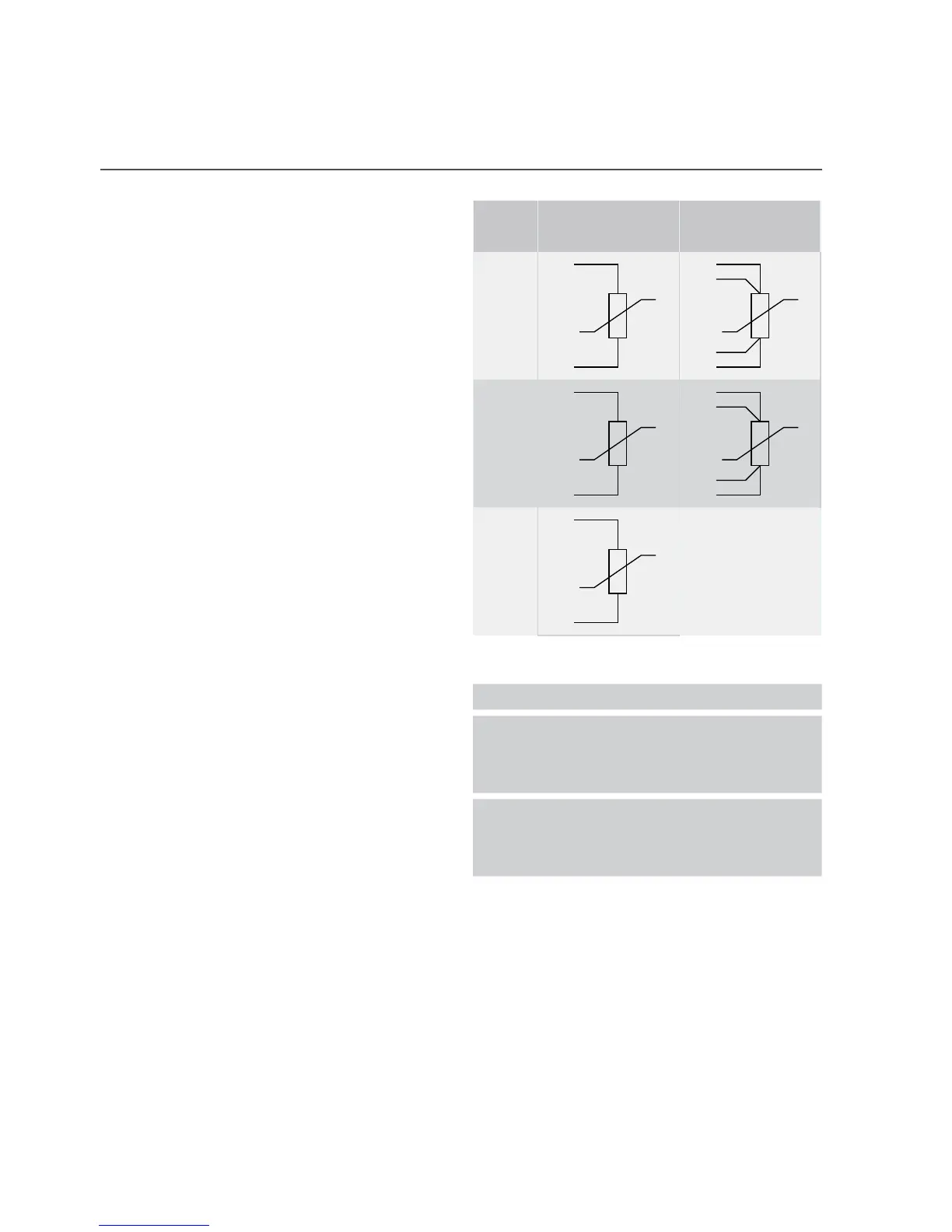
5.1 Connection of temperature sensors
Temperature sensors are connected to
MULTICAL® via the connection PCB. According
to meter type, the terminal numbers in the
table for temperature sensor connection are
used.
2-wire 4-wire
Sensor Terminal number Terminal number
t1
5
6
1
2
5
6
t2
7
8
3
4
7
8
t3
51
52
5.2 Connection of ULTRAFLOW®
ULTRAFLOW® is connected to MULTICAL®
via the connection PCB using the terminal
numbers in the table.
Wire ULTRAFLOW®
9 + Red
V110 Sig Yellow
11 - Blue
9 + Red
V269 Sig Yellow
11 - Blue
5.3 Cable Extender Box
If a cable longer than 10 m is required between MULTICAL® and ULTRAFLOW®, it is possible at
lengths between 10 and 30 m to use Cable Extender Box. See further information in the document
5512-2008.
5.4 Electrical connection of Pulse Transmitter
If ULTRAFLOW® 54 is used together with third-party equipment, it must be connected through a
Pulse Transmitter or Pulse Divider. See instructions 5512-1387 for further information.