7Kamstrup A/S • 55122070_A2_GB_07.2017
MULTICAL® 603
3 Mounting of flow sensor
Prior to installation of the flow sensor, the system should be flushed and protection plugs/plastic
diaphragms removed from the flow sensor.
Correct position of the flow sensor appears either from the calculator’s type label or from the
display where
symbolises the position in inlet, whereas indicates the position in outlet.
The flow direction is symbolised by an arrow on the flow sensor.
3.1 Mounting of couplings and short direct sensor in flow sensor
The short direct sensor from Kamstrup may be
installed in PN16 installations only. Flow sensor
and any mounted blind plug can be used in
connection with both PN16 and PN25. The flow
sensor is available with either PN16 or PN25
marking as required. Enclosed couplings, if
any, are only intended for PN16. Suitable PN25
couplings must be used in PN25 installations.
In connection with flow sensors with the
nominal dimensions G¾Bx110 mm and
G1Bx110 mm, it must be checked if the thread
run-out is sufficient.
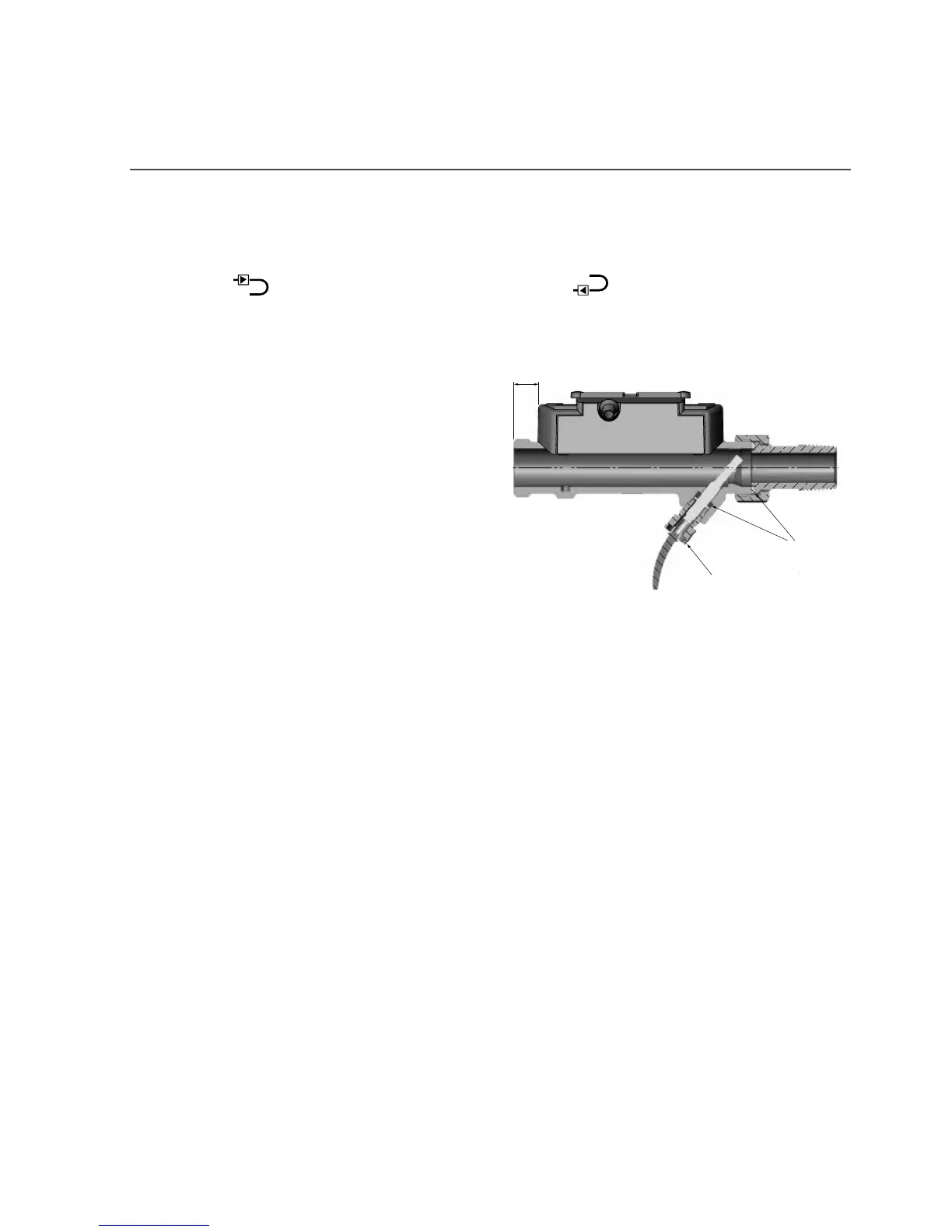
Couplings and gaskets are mounted as shown
in the figure.
Gasket
Moment approx. 4 Nm
12 mm