4544
LCD initializing
message shows
or
sign will not save
messages
Dead Pixels
Message Sign too
dim/bright
Message Sign will
not raise or lower
Message Sign does
not power on
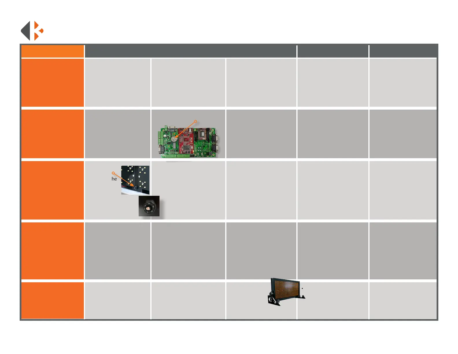
• Open the controller
• Locate
photocell,
bottom of the
display case
panel next
to the power
cord.
• Test for 12V at the power
plug of the actuator motors.
When the sign is supposed to
raise the voltage is positive,
when the sign is supposed to
lower the voltage should go
negative.
If no power:
• Check for connection at the
vehicle’s battery.
If inline fuse was installed:
• Check fuse
• Check for power at the plug,
It should be at least 12V. The
plug is located on bottom of
the frame.
• Ensure the photocell is not
covered by debris.
• Locate CR2032 battery on
the motherboard.
Test boards for pixel outage:
• Create a custom message.
• Type: [cb9] for the yellow
page. Include the brackets
• Press the F9 key.
If there is no power or it is
below 12V:
• Trace power wires and look
for loose connections inside the
message board. 12V will need
to be applied to the motors to
raise them or, they will need
to be dismounted to manually
raise it.
Once all the LEDs are activated:
• Make a note of the boards that
have dead pixels.
VEHICLE MOUNT
TROUBLESHOOTING GUIDE
Please call 888-414-3003 for Tech Support if this guide does not
solve your issue.
• Contact K&K with outage
information for repairs.
The power wire leads to a
small chip inside the board:
• Check for a light to be on.
• Test for power at the ports.
• Main power in should be
12V.
PROBLEM STEP 1 STEP 2 STEP 3 STEP 4 STEP 5
If controller will power up,
but the message board does
not:
• Check the data cable for
signs of damage.
If damaged or burned:
• Replace cord.
• Battery replacement
requires a reset. Custom
messages will be lost. Input
your custom messages
again after replacement.
• Do not leave on
this page for
extended periods
of time. It will
deplete the batteries quickly.
If the problem persists:
• Call K&K Systems for further
Assistance.
If the photocell is not
working:
• Call K&K Systems for a
replacement.
If there is 12V at the chip or
it is not on:
• Call K&K Systems for
further Assistance.
If power is present at plug:
• Open the message sign.
Refer to the wiring diagram
and trace 12V from the power
cord. A 12V battery will have to
be applied to actuators if in the
lowered position.
• Check the battery for at least
3V. Optimal level is 3.2V
• Test photocell with a
ashlight. Hold a ashlight
at the photocell to see if it
brightens up. If it wont dim,
place a piece of electrical tape
over the bulkhead to test if it
dims. Brightness changes have
a short delay
• Replace battery if below 3V.
If dimming does not change:
• Remove the bottom
right LED panel. Trace
wires from photocell back
to motherboard. Refer to
included wiring diagram to
verify wiring on page 52.