13
3.3.5 Motor Overload Protection
The COMBIVERT F5 motor control by default provides motor overload protection at 130% of
the unit’s rated output current. See tables in section 2.3 for rated output current. Two additional
motor overload protection systems are avaialble.
Electronic Motor Overload Protection
This software function provides speed dependent I
2
t overload protection and is approaved by UL
as a solid state overload protection device according to UL508C section 42 and NEC 430 Part
C. The trip current is adjustable as well as whether the motor is self cooled or blower cooled.
Consult the F5B/G Application instruction manual for adjustment details.
Motor Winding Temperature Sensor
• Connects to Terminals T1, T2
• Trip resistance level 1.65...4 kΩ
• Reset resistance level 0.75...1.65 kΩ
• This function can be activated or deactivated through a software parameter. The default setting
is OFF!
• Do not run temperature sensor wires in the same conduit or wire way as other control cables.
These sensor wires most likely are carrying high frequency noise from the motor.
• If the sensor wires are part of the motor cable they must be shielded independently from the
motor wires.
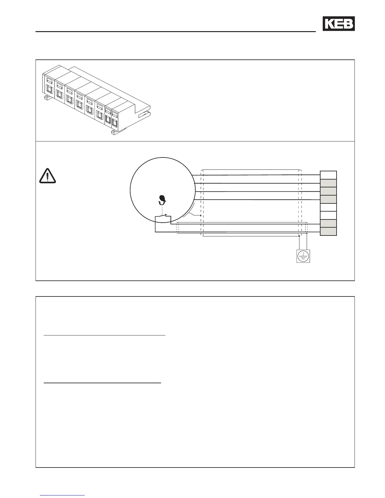
Installation and Connection
3.3.4 Motor connection
The maximum
m o t o r c a b l e
length listed in
the tables in section
2.3 is based on several
factors: use of shielded
motor cables, ground
current limitations,
increased EMI noise
levels, voltage peaks at
the motor terminals.
Connect shield to the mounting
plate with maximum surface area
(use metal cable clamp)
Terminal X1B provides connections for:
• ++, PB Braking resistor
• U, V, W Motor
• T1, T2 Temperature sensor
Terminal strip X1A
Provides connections for:
• 230 V AC / 1-phase (L1/L2)
• 230 V AC / 3-phase (L1, L2, L3)
• DC-Supply 250...370 V DC (++, --)

 Loading...


