17
As an accessory for displaying and editing "CP" parameter values, a
"digital operator" is necessary. To remotely mount the digital operator,
a operator remote cable is required (option: cable 00.F5.0C0-1xxx).
To prevent malfunctions, the inverter must be brought into nOP status
(remove signal from control release terminal 16) before connecting/
disconnecting the operator. When starting the inverter without an
operator, it is started with the last stored values.
4. Operation of
the inverter
Operation of the Drive
4.1 Digital
Operator
Only use the operator interface for the serial data transfer to
RS232, 485. The direct connection from PC to the inverter is only
valid with a special cable (HSP5 Part No. 00.F5.0C0-0001), oth-
erwise it will lead to the destruction of the PC-interface!
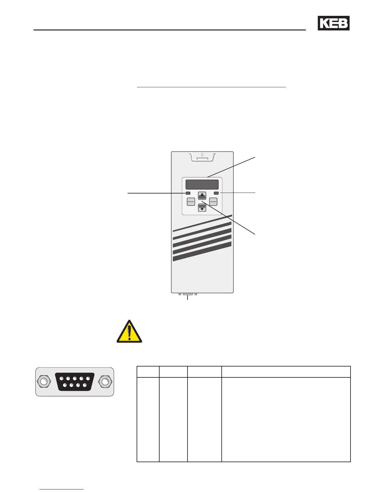
Standard Operator: Part No. 00.F5.060-1000
Serial Operator: Part No. 00.F5.060-2000
Double function keypad
Operating-Error display
Normal "LED on"
Error "LED blinks"
5-digit LED Display
Serial Communication
Transmit "LED on"
(Ref.: 00.F5.060-2000)
RS232, RS485 (Ref.: 00.F5.060-2000)
PIN RS485 Signal Meaning
1 – – reserved
2 – TxD Transmitter signal, RS232
3 – RxD Receiver signal, RS232
4 A' RxD-A Receiver signal A, RS485
5 B' RxD-B Receiver signal B, RS485
6 – VP Voltage supply-Plus +5V
(I
max
= 10 mA)
7 C, C' DGND Data reference potential
8 A TxD-A Transmitter signal A, RS485
9 B TxD-B Transmitter signal B, RS485

 Loading...


