22
This display makes it possible to recognize instantaneous voltage peaks
within an operating cycle. The highest value of CP.7 is stored in CP.8.
The peak value in memory can be cleared by pressing the UP,
DOWN or ENTER key or by writing any value you like to the
address of CP.8. Switching off of the inverter also clears the
peak value.
Display of the actual output voltage in volts rms.
4.5 Basic Ad-
justment of
the Drive
Actual DC voltage
peak value
Output voltage
Minimum
frequency
Maximum fre-
quency
Operation of the Drive
The following parameters determine the fundamental operating data of the
drive. They should be checked and/or adjusted for the application.
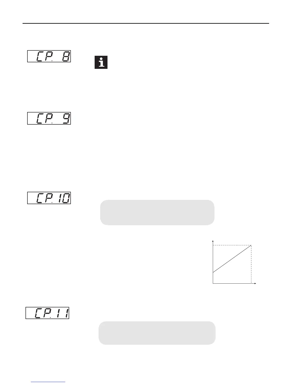
The frequency the inverter outputs with 0V applied to the analog input or if
the activated fixed frequency (CP.19…CP.21) is lower than this value.
Adjustment range: 0...400 Hz
Resolution: 0.0125 Hz
Factory setting: 0.0 Hz
The frequency the inverter outputs with 10V ap
-
plied to the analog input or if the activated fixed frequency (CP.19…CP.21)
is greater than this value.
Adjustment range: 0...400 Hz
Resolution: 0.0125 Hz
Factory setting: 70 Hz

 Loading...


