Installation and Connection
3.3.6 Connection of the braking resistor
Braking resistors can develop very high surface
temperatures, therefore install away from other
devices, above the motor control and where people
can not inadvertantly come in contact with it.
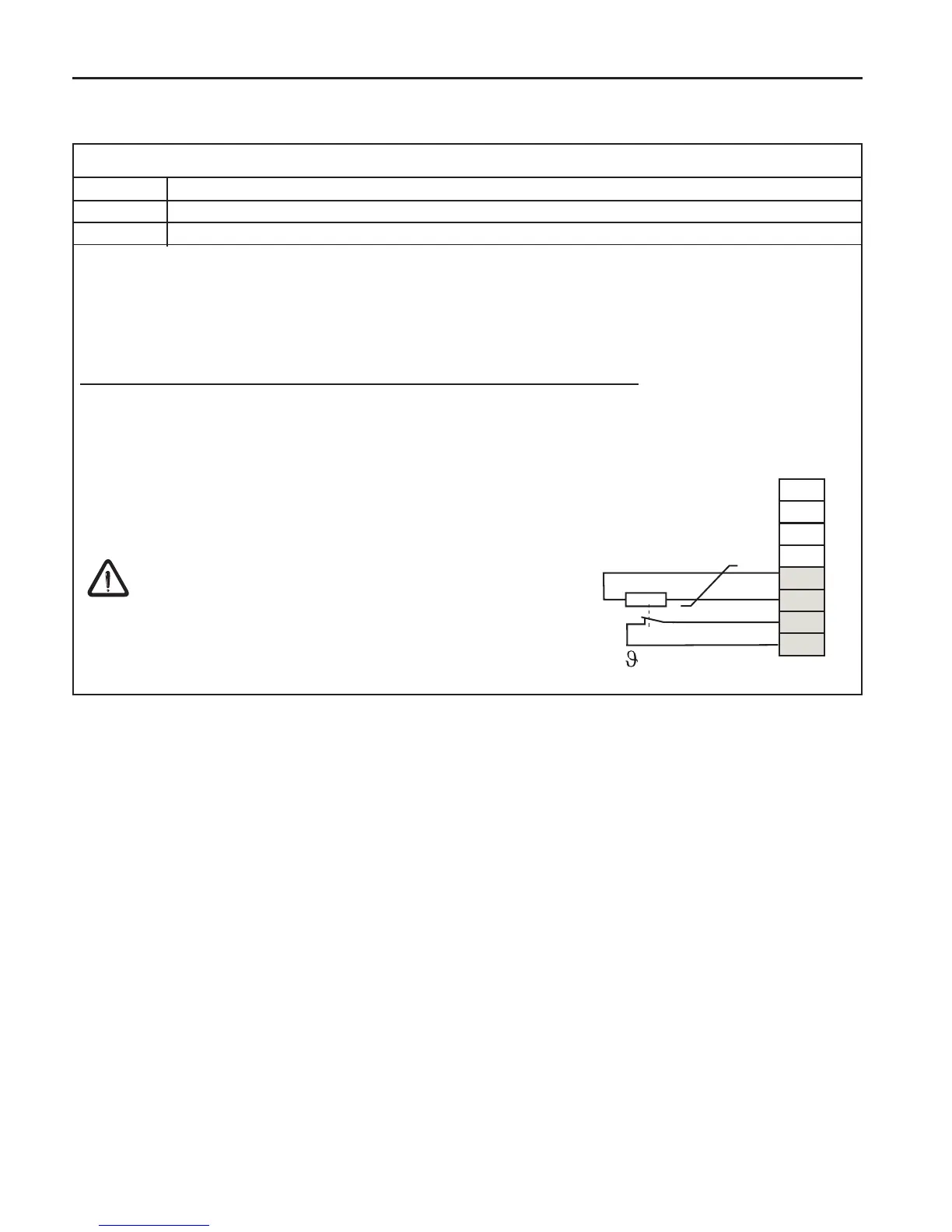
Braking resistor connection with high temperature drive fault
• The resistor has a PTC type sensor and is connected to the T1, T2
terminal on the COMBIVERT F5. If a motor temperature sensor is used
it should be placed in series with the sensor of the braking resistor.
Note: if the braking transistor in the unit fails, there is no guarantee the
voltage to the resistor will be shut off!
Typical braking resistors for A housing COMBIVERT F5 motor controls
F5 Size 230V Class Ohms PD P6
05 07.BR.100-1180 180 44 800
07 07.BR.100-1180 180 44 800
PD = continuous power disapation in watts, P6 = peak repetitive power disapation with a 6
sec on time and 120 sec cycle time. KEB can offer many types of braking resistors, please
contact your sale representative for more information.

 Loading...


