EasyManuals Logo

KEB COMBIVERT F5 Series Installation Guide & Operation Manual

KEB COMBIVERT F5 Series
44 pages
To Next Page IconTo Next Page
To Previous Page IconTo Previous Page
Page #8 background imageLoading...
Page #8 background image
8










































2.4 Dimensions and terminals
Pay attention to the input voltage, since both 230 V and 460 V units (3-phase) are pos-
sible.
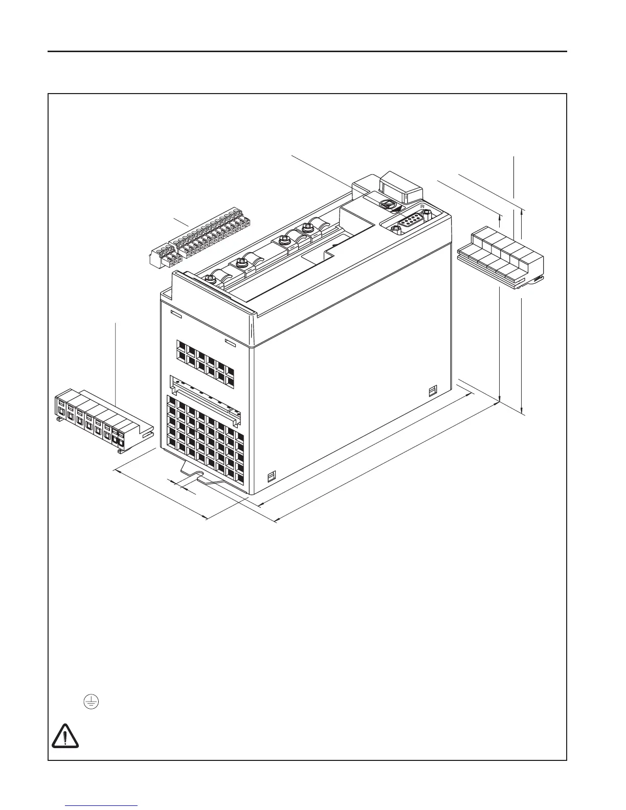
X1A Connection from the line
X1B Connection to the motor, brake resistor, temp sensor
X2A Connectin for control cables
X4A Connection for Operator/display HSP5-Servicecable
Connection for shield / ground
Weight 1/2 kg / 1 lb
Product Description

Other manuals for KEB COMBIVERT F5 Series

Questions and Answers:

Question and Answer IconNeed help?

Do you have a question about the KEB COMBIVERT F5 Series and is the answer not in the manual?

KEB COMBIVERT F5 Series Specifications

General IconGeneral
Control MethodVector Control, V/f Control
Protection ClassIP20
Protection FeaturesOvercurrent, overvoltage, undervoltage, short circuit, overtemperature
Communication InterfacesCAN, PROFIBUS, Modbus RTU
Cooling MethodFan Cooled
Relative HumidityUp to 95% (non-condensing)

Related product manuals