Operating and appliance data
© KEB, 2015-07 COMBIVERT R6-N Page3.2 - 11
3
10
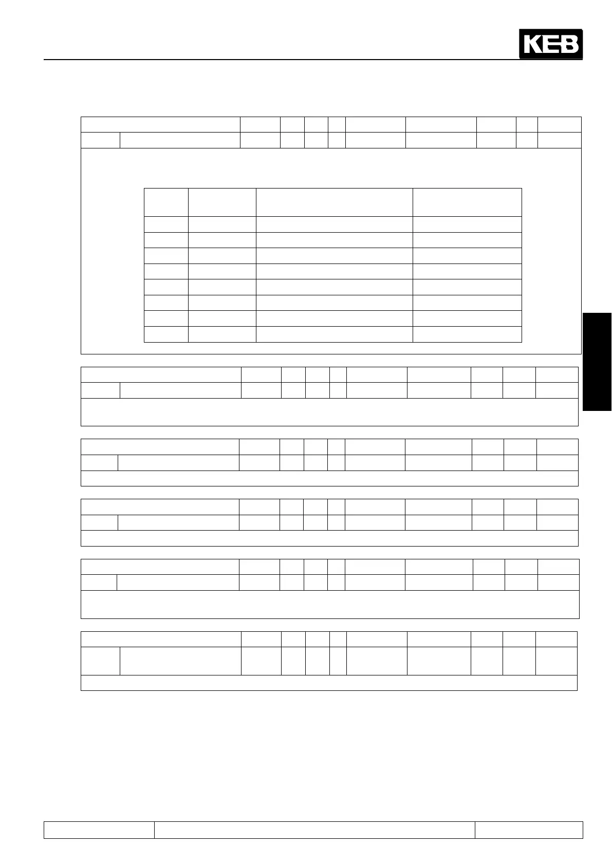
Parameter Addr. R PG E Min. value Max. value Res. [?] Default
ru.80 Digital output state 0250h ro - - 0 255 1 - -
With do.51 the digital output signals can be assigned to the hardware outputs (see chapter 7.3.). This pa-
rameter displays the digital output state of the output signals in accordance with the following table. If several
outputs are set, the sum of the decimal values is displayed.
Bit Decimal
value
Output Terminal
0 1 O1 (transistor output 1) X2A.19
1 2 O2 (transistor output 2) X2A.20
2 4 R1 (relay RLA,RLB,RLC) X2A.24...26
3 8 R2 (relay FLA,FLB,FLC) X2A.27...29
4 16 OA (internal output A) no
5 32 OB (internal output B) no
6 64 OC (internal output C) no
7 128 OD (internal output D) no
Parameter Addr. R PG E Min. value Max. value Res. [?] Default
ru.81 Actual power 0251h ro - - -3200,0 3200,0 0,1 kW 0,0
ru.81 displays the actual power of the COMBIVERT R6. Motor power is displayed with positive values, gen-
eratoric power is displayed with negative values.
Parameter Addr. R PG E Min. value Max. value Res. [?] Default
ru.82 Total net 0252h rw - - 0 2147483647 1 KWh 0
Counter for the regeneratoric electric work to the mains.
Parameter Addr. R PG E Min. value Max. value Res. [?] Default
ru.83 Total motor 0253h rw - - 0 2147483647 1 KWh 0
Counter for the supplied electrical work from the mains.
Parameter Addr. R PG E Min. value Max. value Res. [?] Default
ru.84 Total netMains input 0254h rw - - 0 2147483647 1 KWh 0
Display of the difference between supplied and regeneratoric work. The result is displayed right sign and is
depending on the faulty wiring.
Parameter Addr. R PG E Min. value Max. value Res. [?] Default
ru.85
Actual net /
Mains input
0255h ro - - 0,00 655,35 0,01 kVA 0
Display of the current apparent power at the mains input.
 Loading...
