Operating and appliance data
© KEB, 2015-07 COMBIVERT R6-N Page3.2 - 17
3
10
Parameter Addr. R PG E Min. value Max. value Res. [?] Default
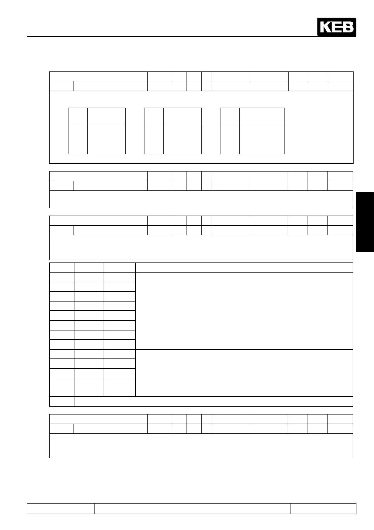
SY.11 Baud rate int. bus 000Bh rw - + 3 10 1 - 5
The transmission speed between operator/inverter or PC/inverter is determined with the internal baud rate.
Followingvaluesarepossible:
Val-
ue
Baud rate Val-
ue
Baud rate Val-
ue
Baud rate
3 9.6 kBaud 6 55.5 kBaud 9 115.2 kBaud
4 19.2 kBaud 7 57.6 kBaud 10 125 kBaud
5 38.4 kBaud 8 100 kBaud
After Power-On it is always started with 38.4 kBaud and dependent on the operator higher set.
Parameter Addr. R PG E Min. value Max. value Res. [?] Default
SY.32 Scope timer 0020h ro - - 0 65535 1 - 0
The scope timer generates a time period of 1 ms. This can be used by external programs, e.g. scope, to rep-
resenttimepatterns.Thetimercountsfrom0...65535andstartsagainwith0afteranoverow.
Parameter Addr. R PG E Min. value Max. value Res. [?] Default
SY.41 Control word high 0029h rw - + 0 65535 1 - 0
The control word is used for status control of the inverter via bus. The control word long (SY.43) consists of
the two 16 bit parameters control word high (SY.41) and control word low (SY.50). The status word is bit-cod-
ed.
Bit Function Value Description
16 I1 1:I1
corresponding input is set via the control word instead via hardware input.
These bits are only effective if the bit for the appropriate input is set in di.01
„select signal source“. Then the OR operation of this bit with the correspond-
ing bits of parameter di.02 " digital input setting" is valid.
17 I2 2:I2
18 I3 4:I3
19 I4 8:I4
20 IA 16:IA
21 IB 32:IB
22 IC 64:IC
23 ID 128:ID
24 O1 256:O1 Appropriate output is set via the control word or via the switching condi-
tions. Die Ausgangssignale O1, O2, R1 und R2 (sichtbar in Parameter ru.80)
werden mit den entsprechenden Bits des Steuerworts ODER verknüpft. The
connection occurs according do.42 „inverted outputs “(inverting level for the
output signals) and before they are switched to the hardware outputs with
do.51 „ hardware output allocation“.
25 O2 512:O2
26 R1 1024:R1
27 R2 2048:R2
28...31 reserved
Parameter Addr. R PG E Min. value Max. value Res. [?] Default
SY.42 Status word high 002Ah ro - - 0 65535 1 - 0
The current condition of the COMBIVERT can be readout with the status word. The status word long (SY.44)
consists of the two 16 bit parameters status word high (SY.42) and status word low (SY.51). The status word
is bit-coded.

 Loading...