34
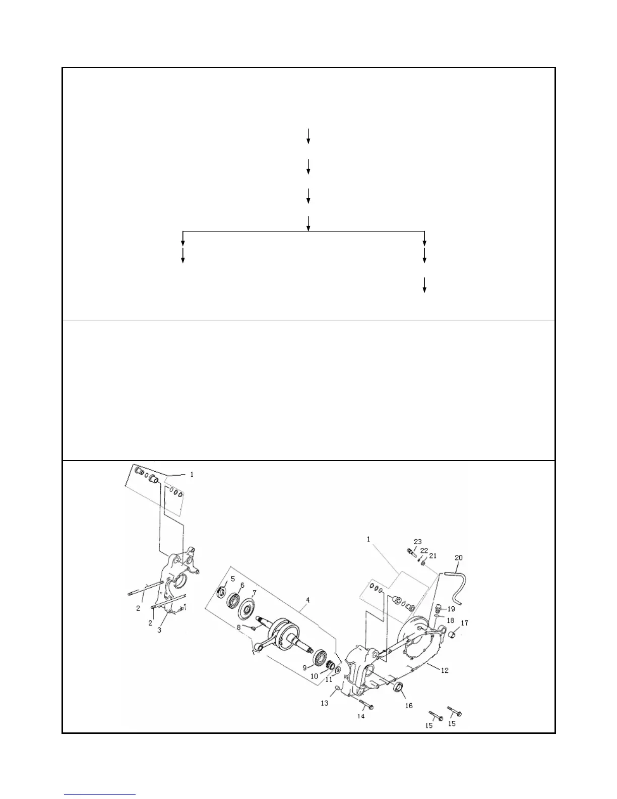
C r a n k c a s e a s s e m b l y
Disassembly:
::
:
Circlip(11)/Piston pin(12)/Piston comp(26)
Bolt 15/Bolt 16/Gear 5
Right crankcase comp(3)/Left crankcase comp(12)/Dowel pin(13)
Crankcase comp(4)/Chain(27)
Damper ( 1 ) /Stud bolt Damper(1)/Stud bolt /Oil seal(16)/Damper(17)
Right crankcase(3) Fixing bearing(23)/Cover of tank hole(19)
Left crankcase(12)
Assembly:
::
:Oppsite to the steps of disassembly.
Instructions:
::
:
1. When assembling the crank, pleae add a little machine oil into the bearing hole of left crankcase, then press it into the
hole upright, and assemble the chain onto the gear of crank, the connecting rod should round freely; There should be
suitable clearance between the big end of connecting rod the fixing bearing.
2. Use woodern or rubber hammer to knock the right crankcase lightly when disassembling and assembling the left and
right crankcase, metal hammer is forbidden to avoid the case.
3. The rear crank connecting rod should round freely without block.
4. The value of torque:10~12 N•m。