1.Spark plug:
::
: Otherwise replace it.
Clean the spark plug in the cleaner and trial 5.Spring loop:
::
:
Run it after cheeking it. Please replace it a.The resistance between the blue white and green
if it has corn down below: white leads should between 100 to 180Ω, otherwise
·Short circuit replace it.
·Abration of electrode b.Replace the spark plug with a L.E.D of 1.5v,
run the magneto the L.E.D should flash,otherwise
2.Cap of spark plug(plug):
::
: replace the spring loop.
Check if the resistance is around 5.0KΩ or 6.C.D.I.part:
::
:
Not, otherwise replace it. a.Test of C.D.I. part: Use C.D.I. working not
well insteading of C.D.I. working well. If the
ATV stark easily, it shows that this part is
in good condition, otherwise replace it.
3.Complex switch:
Use all purpose metre to check the continuity b.Use stroboscope to check the enginery of
between the black white and black leads of ignition, replace it, if it is beyond the
the ignition switch. If it is far away from standerd.
The starderd down below, please replace it.
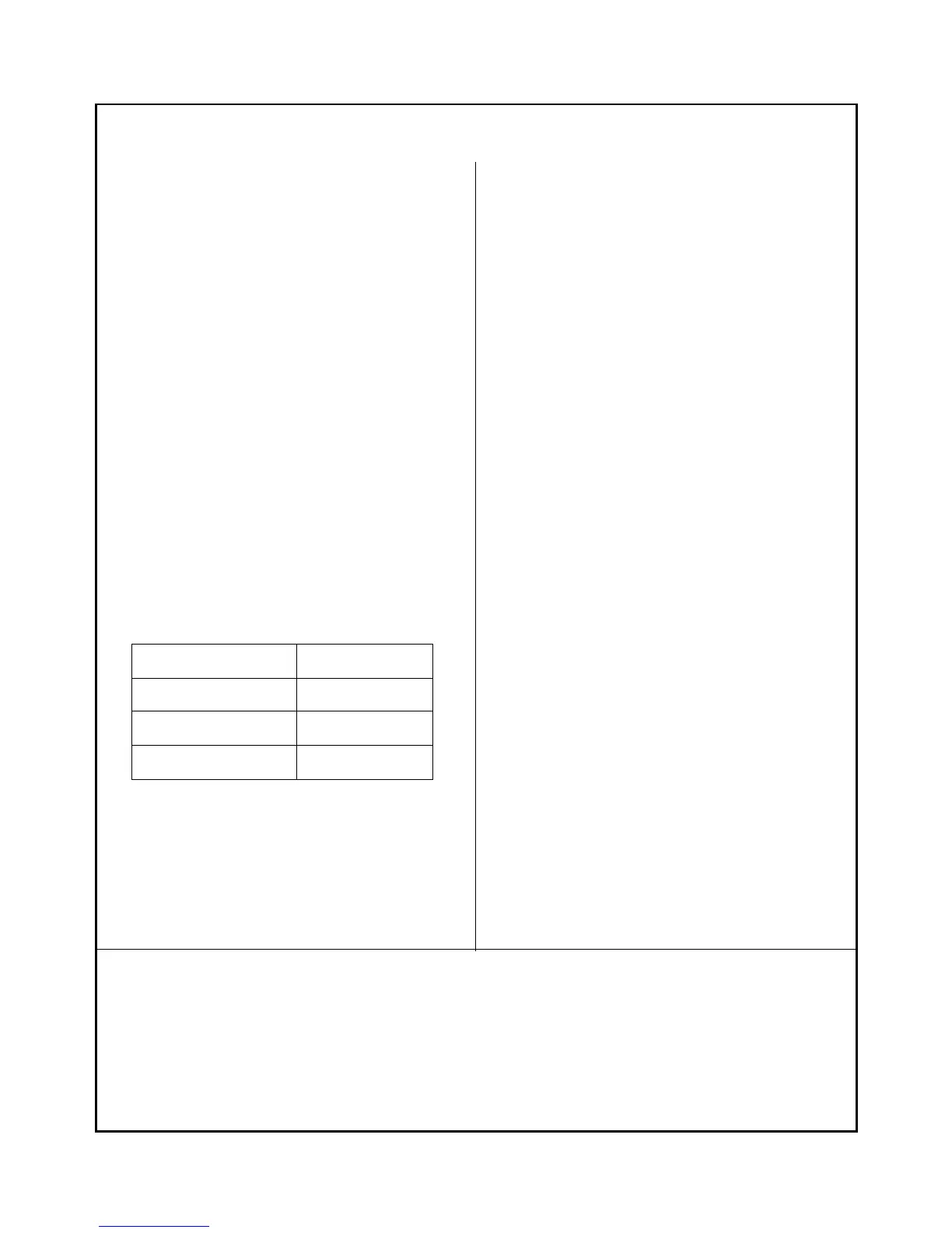
Position of switch State
“OFF” Connect
“LOCK” Connect
“ON” Cut
4.Ignition loop:
::
:
ATV’s ignition loop has sole line connecting
To the ground (black)
a.The resistance between the green and yellow
black primary loop should less than 1.0Ω,
otherwise replace it.