8
For resistance measurements (
Ω
2 and
Ω
4) greater than
100k
Ω
, more stable readings can be achieved by using
shielding. Place the resistance in a shielded enclosure
and connect the shield to INPUT LO. Shielded cable
should be used such that the shield (INPUT LO) encir-
cles the other cable conductor(s).
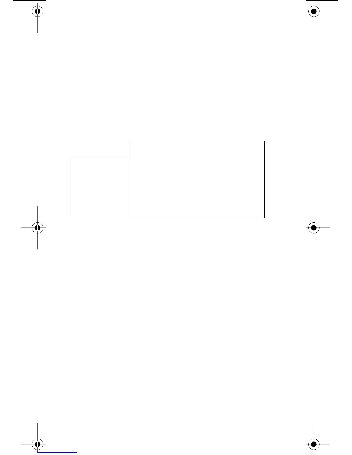
Maximum inputs for the Model 2000 are summarized in
Table 1.
Basic measurement procedure
1. Connect the instrument as explained in “Instrument
connection”.
2. From the function keys, select the desired measure-
ment function.
3. Use the RANGE keys to select autoranging or a
manual range. Pressing the AUTO range key tog-
gles autoranging. You can select a different range
with the
▲
and
▼
RANGE keys.
4. Take a reading from the display.
Table 1. Maximum inputs
Function Maximum input
DCV 1000V peak
ACV 750V rms, 1000V peak, 8
×
10
7
V•Hz
DCI 3A dc, 250V
ACI 3A rms, 250V
FREQ (PERIOD) 1000V peak, 8
×
10
7
V•Hz
2000-903-01A Page 8 Thursday, December 23, 1999 7:52 AM