Section 2: Using the front-panel interface Model 2651A High Power System SourceMeter® Instrument User's Manual
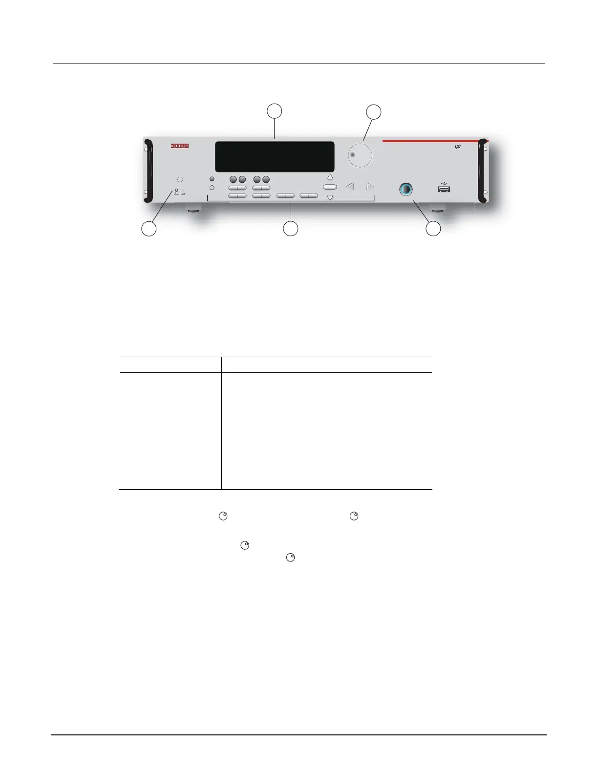
Figure 1: Front panel
CURSOR
SRC MEAS LIMIT MODE
POWER
AUTO
O
U
T
P
U
T
O
N
/
O
F
F
2651A HIGH POWER SYSTEM SourceMeter
®
12 3
4
DISPLAY
CONFIG
56
78 9
0
+/-
0000
SPEED
DIGITS
FILTER
REL
RECALL
STORE
MENU
TRIG
ENTER
LOCAL
EXIT
RUN
LOAD
P
U
S
H
T
O
E
D
I
T
/
E
N
T
E
R
P
U
S
H
T
O
E
D
I
T
/
E
N
T
E
R
2
5
3
4
1
+3.21000V
ARM
SrcA:+20.0000 A LimAL10.0000V
(1) The POWER key. Press this key to turn the instrument on (|). Press it again to turn the instrument
off (0).
(2) The display. During operation, the display provides readings and information about the selected
measurement and configuration. It also shows the control status (local or remote). If REM is
displayed, the instrument is being controlled remotely (through GPIB, LAN, or USB). If REM is not
displayed, control is through the front panel.
During setup, the display shows menu choices that you can use to configure the instrument.
The items listed below represent the possible display indicators and what they mean.
Indicator Meaning
EDIT: Unit is in the source editing mode
ERR: Questionable reading or invalid calibration step
REM: Unit is in remote mode
TALK: Unit is addressed to talk
LSTN: Unit is addressed to listen
SRQ: Service request is asserted
REL: Relative mode is enabled
FILT: Digital filter is enabled
AUTO: Source or measure autorange is selected
* (asterisk): Readings are being stored in the buffer
(3) The navigation wheel . Turn the navigation wheel to scroll to a menu option or to change the
selected value.
Push the navigation wheel
to open menus or to select a menu option or a value. In most
cases, pressing the navigation wheel
performs the same action as pressing the ENTER key.
(4) The OUTPUT ON/OFF control. Press this control to turn the Model 2651A source output on or off.
The output indicator will light when the source is on.
(5) The setup and control keys provide front panel control and configuration. The following figure
illustrates each key's location. The table following the figure contains a definition of each key.
2-2 2651A-900-01 Rev. A / March 2011
 Loading...


