Front Panel Operation
2-126
B. Card installed in option slot — Select the PER-
FORM-SCAN option from the menu and select EX-
TERNAL scanning.
NOTE
The CHANNEL-CLOSURES option is
used to open/close channels on the scanner
card installed in the option slot. For details,
see the instruction manual for that card.
The displayed message will prompt you to reset the
external scanner. Press ENTER when ready.
4. The next message will prompt you to set the channel
count (CHAN COUNT) of the external scanner to infi-
nite. Press ENTER when ready.
5. The next message will prompt you to select the trigger
source for the Model 6517A:
SELECT TRIG SOURCE
TRIGLINK EXTERNAL TIMER GPIB
MANUAL IMMEDIATE
These trigger sources are explained in paragraph 2.15.
6. The next message will prompt you to set the external
scanner to the trigger source that you selected in step 6
for the Model 6517A. Press ENTER when ready.
7. The next message will prompt you to set the scan list of
the external scanner for the appropriate number of chan-
nels. This is the same number of external inputs that was
specified in step 2. Press ENTER when ready.
8. The next message will prompt you to STEP the external
scanner to the first channel. Press ENTER when ready.
9. The next message will prompt you to set the scan count
for the Model 6517A. The scan count specifies how
many times you wish to repeat the scan. For example, if
the scan list has 40 channels, and the scan count is 5,
then 40 channels will be scanned five times. Press EN-
TER when ready.
10. The next message will ask if you wish to use the scan
timer of the Model 6517A. If you selected TIMER as the
trigger source in step 6, select YES. You will then be
prompted to enter the interval between triggers (0.001
sec to 999999.999 sec). Otherwise, select NO.
11. The next message will ask if you wish to store the read-
ings in the buffer. If you select YES, the number of read-
ings that will be stored in the buffer will be displayed.
Note that the buffer size is limited (see paragraph 2.16
for details).
12. The last message prompts you to start the external scan
by pressing ENTER. The selected trigger source will
control the scan. Note that the TRIG key is always active
to allow you to step through the scan.
2.21 Other measurement considerations
The following measurement considerations apply to all pre-
cision measurements. For comprehensive information on all
measurement considerations, refer to the Low Level Mea-
surements handbook, which is available from Keithley.
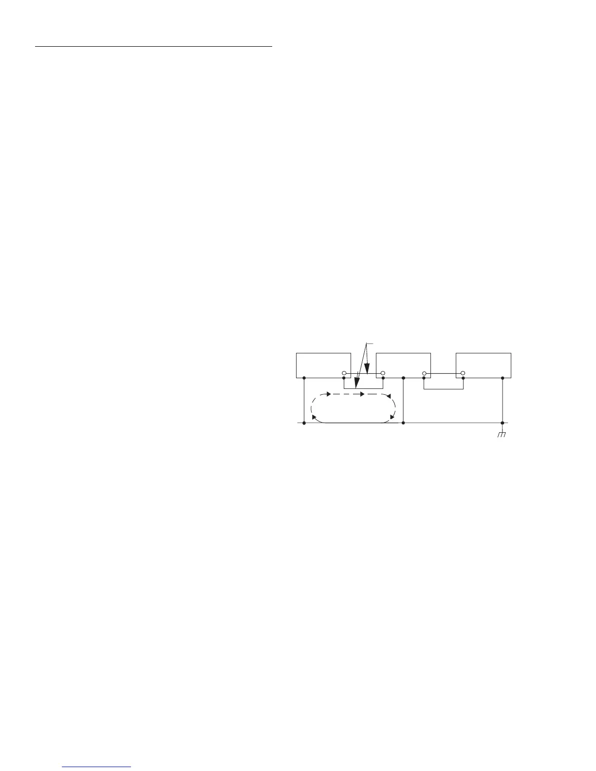
2.21.1 Ground loops
Ground loops that occur in multiple-instrument test set-ups
can create error signals that cause erratic or erroneous mea-
surements. The configuration shown in Figure 2-83 introduc-
es errors in two ways. Large ground currents flowing in one
of the wires will encounter small resistances, either in the
wires, or at the connecting points. This small resistance re-
sults in voltage drops that can affect the measurement. Even
if the ground loop currents are small, magnetic flux cutting
across the large loops formed by the ground leads can induce
sufficient voltages to disturb sensitive measurements.
To prevent ground loops, instruments should be connected to
ground at only a single point, as shown in Figure 2-84. Note
that only a single instrument is connected directly to power
line ground. Experimentation is the best way to determine an
acceptable arrangement. For this purpose, measuring instru-
ments should be placed on their lowest ranges. The configu-
ration that results in the lowest noise signal is the one that
should be used.
Power Line Ground
Signal Leads
Typical ground loop
causes current flow
in a signal lead
Instrument
A
Instrument
B
Instrument
C
Figure 2-83
Multiple ground points create a ground loop