Front Panel Operation
2-120
LOW). This is programmed from the DIGOUT selection of
the GENERAL menu.
2.19.6 STATUS-MSG
This selection is used to enable or disable the status messag-
es mode. When enabled, status messages are displayed to
identify specific operations that are performed.
ON: Enable the status message mode.
OFF: Disable the status message mode.
The instrument may become so busy displaying status mes-
sages, that key presses are no longer acknowledged. You
may have to clear status message display by pressing the
EXIT key or sending a bus command (:DISPlay:SMESsage
OFF) to get out of this mode.
Tolerance
Bands
±10%
±1%
Resistance
Bit
Patterns
and
Limits
90kΩ 99kΩ 101kΩ 110kΩ
001 011 000 100 010
LOLIM1 LOLIM2 HILIM2 HILIM1
Figure 2-78
Using limit test to sort 100k
Ω
resistors
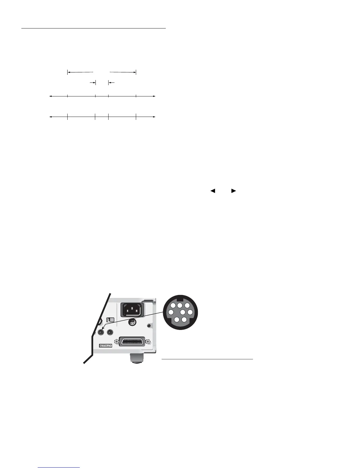
1 = +5V (with 510Ω series resistor)
2 = Data In (calibration fixture use*)
3 = V
EXT
flyback connection (+5V to +30V)
4 = Digital output #1
5 = Digital output #2
6 = Digital output #3
7 = Digital output #4
8 = Digital ground
*Pin 2 is for use with Model 5156 Calibration Source
Pin Designation
DIGITAL
OUT
(Connector J1015)
WARNING:
NO INTERNAL OPERATOR SERVICABLE PARTS,SERVICE BY QUALIFIED PERSONNEL ONLY.
WARNING:
NO INTERNAL OPERATOR SERVICABLE PARTS,SERVICE BY QUALIFIED PERSONNEL ONLY.
CAUTION:
FOR CONTINUED PROTECTION AGAINST FIRE HAZARD,REPLACE FUSE WITH SAME TYPE AND RATING.
CAUTION:
FOR CONTINUED PROTECTION AGAINST FIRE HAZARD,REPLACE FUSE WITH SAME TYPE AND RATING.
INPUT
250V PEAK
!
LINE RATING
50-60HZ
50VA MAX
AC ONLY
LINE FUSE
SLOWBLOW
1/2A 90-125V
1/4A 180-250V
IEEE-488
(CHANGE IEEE ADDRESS
WITH FRONT PANEL MENU)
DIGITAL
I/O
TRIG LINK
115V
1
2
3
4
5
6
7
8
igure 2-79
igital I/O port
2.19.7 GENERAL
The GENERAL menu is used for the following operations:
•To control the state and sense of the digital outputs.
•To view the serial number, SCPI version, and firmware
revision levels of the Model 6517A.
•To set line synchronization of readings, display the fre-
quency of the line power, and configure the A/D to
measure humidity and/or external temperature.
•To configure timestamp.
•To choose the character displayed for a decimal and se-
lect measurement units.
•To set the real-time clock.
DIGOUT (Digital I/O menu)
Access the DIGOUT menu as follows:
1. From the main menu, select the GENERAL menu.
2. Use the and keys to highlight DIGOUT, and
press Enter. The following will be displayed:
DIGOUT
STATE LOGIC-SENSE
Digital I/O port
The Model 6517A’s Digital I/O port is an 8-pin mini-DIN
socket located on the rear panel. The port’s location and pin
designations are shown in Figure 2-79.