Front Panel Operation
2-18
Handling and cleaning test fixtures
Dust, body oil, solder flux and other contaminants on con-
nector and terminal insulators can significantly decrease the
leakage resistance resulting in excessive leakage currents.
Also, contaminants on DUT and test circuit components can
create a leakage path. These leakage currents may be large
enough to corrupt low-level measurements.
Handling tips:
• Do not touch the bodies of DUT or test circuit compo-
nents. If you cannot handle them only by their leads, use
clean cotton gloves to install them in the test fixture.
• Do not touch any connector or terminal insulator.
• If installing a test circuit that is on a pc-board, handle
the board only by the edges. Do not touch any board
traces or components.
Cleaning tips:
• Use dry nitrogen gas to clean dust off of connector and
terminal insulators, DUT and other test circuit compo-
nents.
• If you have just built the test fixture, remove any solder
flux using methanol along with clean foam-tipped
swabs or a clean soft brush. Clean the areas as explained
in the next tip.
•To clean contaminated areas, use methanol and clean
foam-tipped swabs. After cleaning a large area, you
may want to flush the area with methanol. Blow dry the
test fixture with dry nitrogen gas.
• After cleaning, the test fixture (and any other cleaned
devices or test circuits) should be allowed to dry in a
50°C low-humidity environment for several hours.
2.5 Voltage measurements
The Model 6517A can make unguarded or guarded voltage
measurements from 1µV to 210V. Guard should be used if re-
sponse time or leakage resistance is a consideration. The con-
cepts of guarding are discussed in paragraphs 2.4.4 and 2.5.3.
2.5.1 Basic measurement procedure
The voltage measurement procedure is summarized as follows:
NOTE
To ensure proper operation, always enable
zero check ("ZeroCheck" displayed) be-
fore changing functions (V, I, R, or Q).
The Z-CHK key controls zero check.
1. With zero check enabled (“ZeroCheck” displayed), se-
lect the volts (V) function. The Z-CHK key toggles zero
check between the on and off states.
NOTE
The input circuit configuration changes
with zero check enabled. See paragraph
2.13 for details.
2. Enable or disable guard as needed. Guard is controlled
from the GUARD option of the Voltage Configuration
menu (see paragraph 2.5.2).
NOTE
The “Grd” message on the display indi-
cates that guard is enabled (on).
3. To achieve optimum accuracy for low voltage measure-
ments, it is recommended that you zero correct the instru-
ment. To do so, select the lowest measurement range (2V)
and press REL. The REL indicator turns on and the
“ZCor” message is displayed. Correcting zero on the low-
est range will correct all ranges because of internal scaling.
NOTE
If guard is enabled, the “ZCor” message
will replace the “Grd” message. Keep in
mind that guard is still enabled even
though the “Grd” message is not displayed.
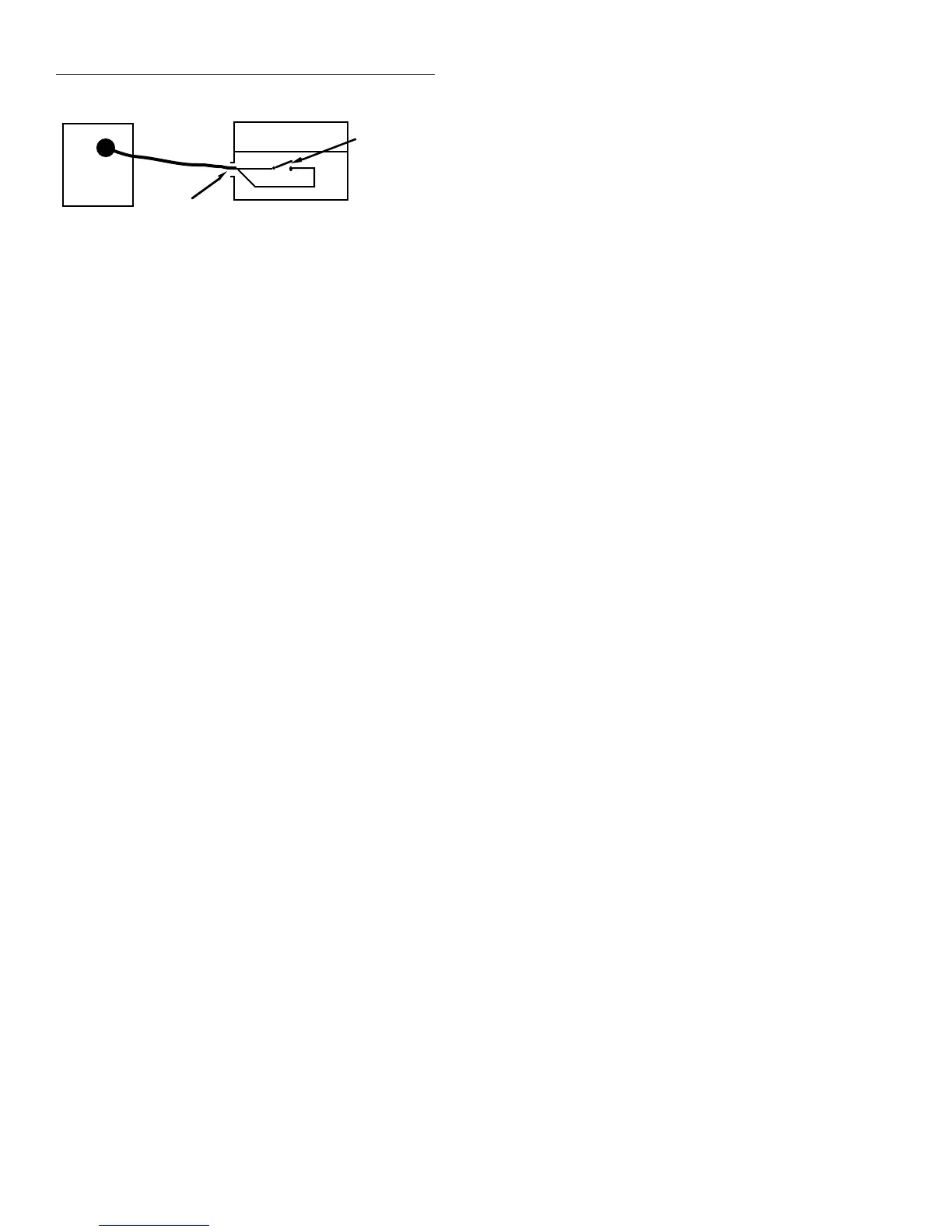
6517A
Interlock
6517-ILC-3 Cable*
Test Fixture
* Plu
at test fixture end of cable removed
Clear
Black
Normally-Open
SPST Momentary
Switch
Strain relief for cable
Figure 2-19
Hard-wired interlock