Front Panel Operation
2-4
Depending on the installed memory option, either one, five,
or ten user-defined setups can be stored, any one of which
could be selected as the power-on default.
Table 2-30 in paragraph 2.19.1 lists the default conditions
that are set at the factory to optimize bench and GPIB (IEEE-
488) operation.
2.2.5 Warm-up period
The Model 6517A can be used within one minute after it is
turned on. However, the instrument should be turned on and
allowed to warm up for at least one hour before use to
achieve rated accuracy.
2.2.6 IEEE-488 primary address
The IEEE-488 primary address of the instrument must be the
same as the primary address you specify in the controller's
programming language. The default primary address of the
instrument is 27, but you can set the address to any value
from 0 to 30 by using the MENU key. Refer to paragraph
2.19.2 for step-by-step instructions on setting the primary
address.
2.3 Display
The display of the Model 6517A is primarily used to display
readings along with the units and type of measurement.
When not displaying readings, it is used for informational
messages, such as menu headings and selections. At the top
of the display are annunciators to indicate various states of
operation.
2.3.1 Exponent mode (Engineering or Scientific)
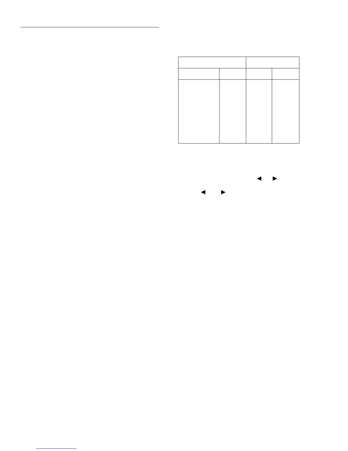
Readings on the display can be expressed in engineering
units or in scientific notation as shown in Table 2-4. In the
scientific mode, the exponent can be fixed to a specified val-
ue, or it can be floating. In the floating mode, the instrument
will automatically select the exponent value.
All exponent mode selections are performed from the DIS-
PLAY option of the GENERAL menu, which is part of the
MAIN MENU (see paragraph 2.19.7 for details).
2.3.2 Information messages
Press the INFO key to view context-sensitive information
from most of the displays. An arrow ( or ) on the bot-
tom line indicates that there is more information. Use the
cursor keys ( and ) to view the complete line. To exit
an INFO display, just press INFO, ENTER, EXIT or a func-
tion key.
Range messages
The following display messages may occur when making
measurements:
OVERFLOW — This message is displayed when the inte-
grated (average) input signal level (voltage, current, or
charge) exceeds 105% of full scale for the selected measure-
ment range. For example, on the 20nA measurement range,
the OVERFLOW message occurs when the integrated input
level exceeds 21nA.
An OVERFLOW condition can be resolved by selecting a
higher measurement range, using AUTO range, or reducing
the magnitude of the input signal.
The OVERFLOW message will NOT occur during resis-
tance or resistivity measurements.
UNDERFLOW — This condition is similar to OVER-
FLOW but pertains to resistance and resistivity measure-
ments. An ohms measurement is performed by sourcing
voltage and measuring current. An ohms measurement that is
too low causes the current to exceed full scale. Thus, the
message UNDERFLOW is used to indicate that the mea-
sured resistance or resistivity is lower than the lower limit of
the selected range.
Table 2-4
Typical display exponent values
Engineering units Scientific notation
Value Display Value Display
Picoamperes
Nanocoulombs
Microamperes
Milliamps
Kilo-ohms
Mega-ohms
Giga-ohms
Tera-ohms
Peta-ohms
pA
nC
µA
mA
kΩ
MΩ
GΩ
TΩ
PΩ
10
-12
A
10
-9
C
10
-6
A
10
-3
A
10
3
Ω
10
6
Ω
10
9
Ω
10
12
Ω
10
15
Ω
e-12A
e-9C
e-6A
e-3A
e3Ω
e6Ω
e9Ω
e12Ω
e15Ω