SERVICE MANUAL
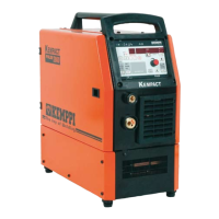
KEMPACT RA_V_1.2
12 (40)
Kemppi Oy
3. DESCRIPTION OF OPERATIONS
Kempact RA welding machine consists of several circuit cards and separate components. In the following sections are
described the main components and separate cards functions.
Machine basic function (machine start up), after mains voltage is switched on:
1. DC-link capacitors are charged and if there is no over voltage condition inrush relay is switched on after a short delay
2. If there is PFC circuit it’s enabled after a short delay
3. Fans are started for a test run after a short delay
4. Welding is enabled
Kempact RA machines have following parts and components:
• Terminal block X001
• Varistors R001
• Main switch S001
• Terminal block X009
• Main circuit card Z001
o EMC filter
o Inrush current limiting
o IGBT driver
o Current transformer T1
o Main circuit
• PFC choke L002 (181-, 251-, 253MV- and 323MV-models)
• PFC circuit auxiliary transformer T003 (181-, 251-, 253MV- and 323MV-models))
• Test connector X006
• Auxiliary transformer T002
• Rectifier bridge G003
• Control card A001
• Cooling fans M001 and M002
• Gas valve Y001
• Wire feed motor M003
• Brights led card P002
• Panel card P001
• Main circuit card Z001
• Secondary rectifier card Z002
• Secondary choke L001
• Output RFI filters C001 and C002
• Euro connector X005
 Loading...