SERVICE MANUAL
KEMPACT RA_V_1.2
31 (40)
Kemppi Oy
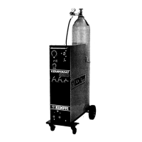
8.2. Kempact 253, 323
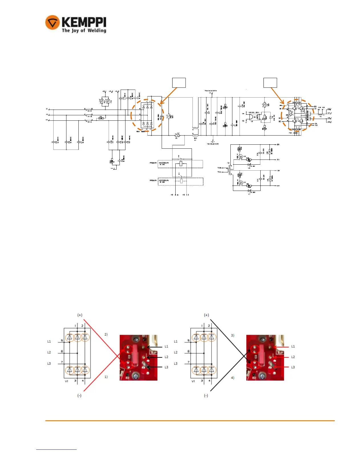
8.2.1. Primary rectifier, V1
• Primary side primary rectifier diodes can be measured one at the time
• Diodes must be measured both forward bias and reverse bias condition to make sure they are fine
• Check the diodes using the multimeter diode function to measure their threshold voltage 0,3…0,6 V
Measurings:
1) Positive test pole to DC-link (-), negative test pole to L1, L2, L3 (one at the time)
Result: 0,3…0,6diodes Ok
2) Positive test pole to DC-link (+), negative test pole L1, L2, L3 (one at the time)
Result: no valuediodes Ok
3) Negative test pole to DC-link (+), positive test pole L1, L2, L3 (one at the time)
Result: 0,3…0,6diodes Ok
4) Negative test pole to DC-link (-), positive test pole L1, L2, L3 (one at the time)
Result: no valuediodes Ok
 Loading...