SERVICE MANUAL
KEMPACT RA_V_1.2
29 (40)
Kemppi Oy
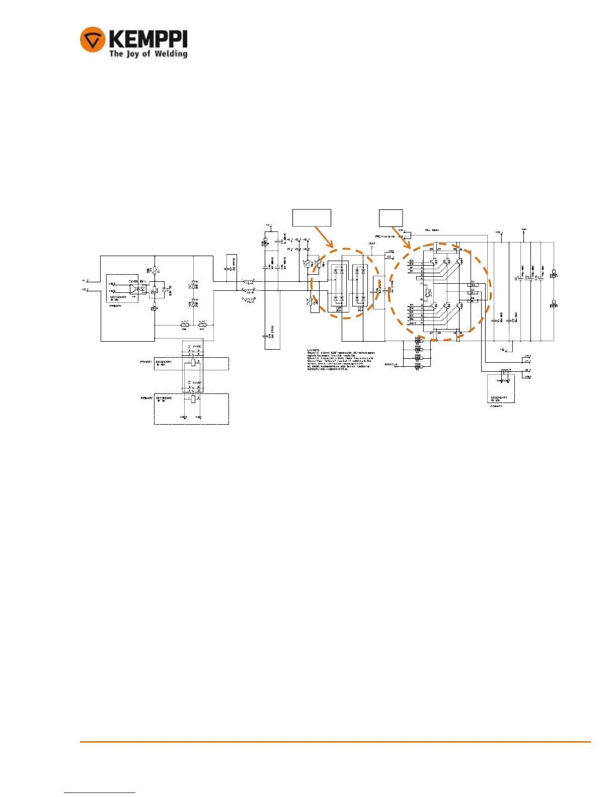
8. OPERATIONAL MEASURINGS AND TESTS
NOTE !
Main supply voltage must not be connected when making measuring operations. The component frame has to be uninstalled
so that main components conditions can be measured.
8.1. Kempact 181, 251
8.1.1 Primary rectifier V24, 25
• Primary side primary rectifier diodes can be measured one at the time
• Diodes must be measured both forward bias and reverse bias condition to make sure they are fine
• Check the diodes using the multimeter diode function to measure their threshold voltage 0,3…0,6 V
Measurings :
1) Positive test pole to rectifier pole (1, red), negative test pole to rectifiers poles (1, black) one at time
Result: 0,3…0,6diodes Ok
2) Negative test pole to rectifier pole (2, black), positive test pole to rectifier poles (2, red) one at the time
Result: no valuediodes Ok
3) Negative test pole to rectifier pole (3, black), positive test pole rectifier poles (2, red)one at the time
Result: 0,3…0,6diodes Ok
4) Positive pole to rectifier pole (4, red), negative test pole to rectifier poles (1, black) one at the time
Result: no valuediodes Ok
NOTE !
The measurement procedure is same for V24 and V25 rectifiers.
 Loading...