Promig 530 / 0612 – 25© kemPPi oy
Filler wire Shielding gas
Welding of steel
ø 1,0 mm, solid wire 75...82 % Ar + 25...18 % CO
²
ø 1,2 mm, solid wire 75...82 % Ar + 25...18 % CO
²
ø 1,2 mm, cored wire 75...82 % Ar + 25...18 % CO
²
Note!
100 % CO
2
is welded by setting welding dynamics to positions 8...9
Welding of stainless steel
ø 0,8 mm, 307, 308, 309, 316 97,5...98 % Ar + 2,5...2 % CO
²
/O
²
ø 1,0 mm, 307, 308, 309, 316 97,5...98 % Ar + 2,5...2 % CO
²
/O
²
ø 1,2 mm, 307, 308, 309, 316 97,5...98 % Ar + 2,5...2 % CO
²
/O
²
Welding of aluminium
ø 1,0 mm, AlMg5, AlSi5 100 % Ar
ø 1,2 mm, AlMg5, AlSi5, Al99,5 100 % Ar
ø 1,6 mm , AlMg5, AlSi5, Al99,5 100 % Ar
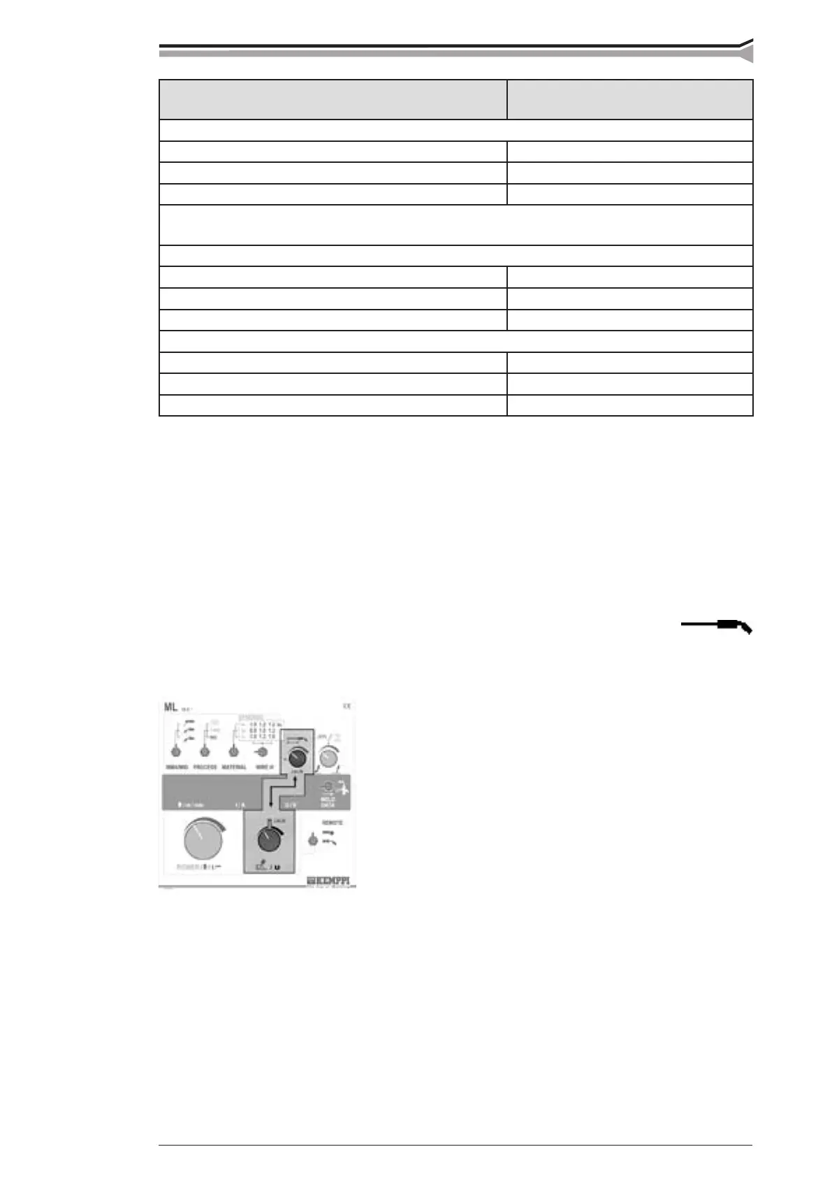
In SYNERGIC MIG welding the welding values are adjusted with power potentiometer (normally
potentiometer for wire feed speed), arc length potentiometers (normally voltage potentiometer)
and welding dynamics potentiometer. Min. and max. power optimized for each wire correspond
to min. and max. setting of power adjustment potentiometer. Set values connected with these min.
and max. powers are shown in set value displays.
Compensating cable length
By compensation of cable length the voltage losses which arise in long interconnecting cables and
different welding guns are taken into account. Cable compensation is adjusted as follows:
If interconnecting cables between wire feed unit and power
source are not used, set cable compensation at position
zero.
If the zero position doesn’t operate as you want to, make
adjustment check as described in following.
When using interconnecting cables, make as follows:
1. Adjust arc length at = CAL, which corresponds to normal arc length
2. Weld at power level wanted by you
3. Adjust with potentiometer for cable compensation a suitable arc length
4. Check adjustment range for arc length by adjusting arc length -9...0...9
5. When needed repeat points 2...4
 Loading...