24 – Promig 530 / 0612 © kemPPi oy
MIG
1-MIG
Note! Display shows terminal voltage of power source. Depending on length and copper cross-
section of welding cables as well as on that of MIG guns real arc voltage and display might differ
many volts from each other, see table below.
Cable 50 mm2 70 mm2 95 mm2
Voltage loss / 10 m 0,35 V / 100 A 0,25 V / 100 A 0,18 V / 100 A
When you adjust welding dynamics, display shows adjustment value for welding dynamics
-9...0...9 and value is kept on display still for approx. 3 s after end of adjustment. After that display
is retrieved to show voltage in SYNERGIC MIG and MMA welding and arc length in SYNERGIC
PULSED MIG welding.
3.2.1. WELD DATA
Retrieval of welding parameters to displays,
Use of WELD DATA switch retrieves to displays those welding parameters, wire feed speed, welding
current, welding voltage which were used when welding was stopped last. Welding values are
indicated in display for so long as you are using the WELD DATA switch and are kept in memory
until you press again the start switch for gun.
Testing the gas ow
A short press on the switch starts the ow of the shielding gas. The shielding gas ows for
approximately 20 seconds, or until the switch is pressed again.
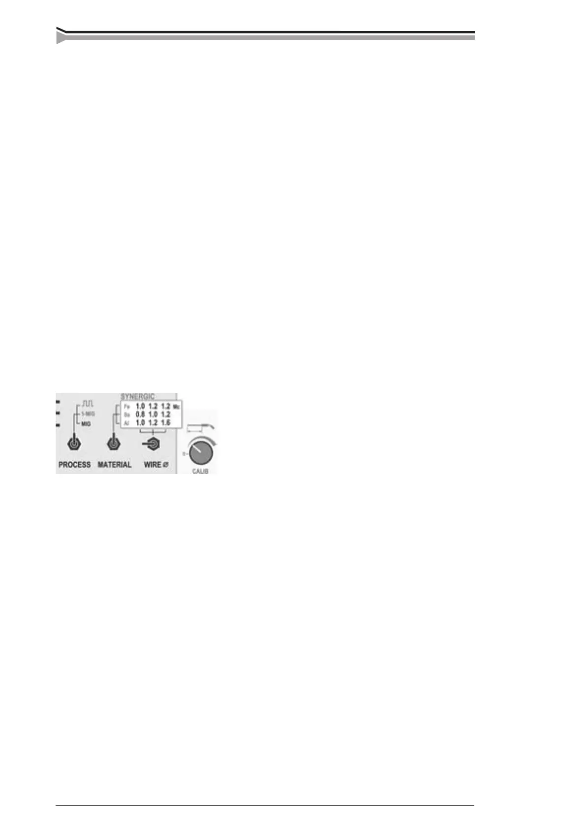
3.2.2. SYNERGIC operations, ML panel
In SYNERGIC operation the operator tells the equipment the ller wire type and diameter which
are used and the equipment generates on basis of these data optimal welding characteristics for
wire in question. In SYNERGIC state adjustment for wire feed changes as adjustment for welding
power and adjustment for voltage changes as adjustment for arc length (so called ”one knob
adjustment”).
In SYNERGIC operation there are three operation modes:
Normal MIG/MAG welding with independent adjustments for wire feed speed
and voltage. SYNERGIC operation is not in use.
SYNERGIC MIG welding with parameters which are optimized according
to ller wire parameters. Nine SYNERGIC MIG programs for different ller
wires are stored:
 Loading...