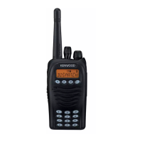
Do you have a question about the Kenwood TK-3170 E and is the answer not in the manual?
| frequency range | 440~470MHz (E) 470~512MHz (X2) |
|---|---|
| number of channels | Max. 128 per radio |
| channel spacing | E: Wide 5k: 25kHz, Wide 4k: 20kHz, Narrow: 12.5kHz; X2: Wide: 25kHz, Narrow: 12.5kHz |
| battery voltage | 7.5V DC ± 20% |
|---|---|
| battery life (KNB-24L 1400mAh) | 9 hours |
| battery life (KNB-25A 1200mAh) | 8 hours |
| operating temperature range | –30°C~+60°C |
|---|---|
| frequency stability | ± 0.00025% (–30°C~+60°C) |
| antenna impedance | 50Ω |
| sensitivity EIA 12dB SINAD (Wide 5k) | 0.25µV |
|---|---|
| sensitivity EIA 12dB SINAD (Narrow) | 0.32µV |
| adjacent channel selectivity (Wide 5k) | 70dB |
| RF power output (HI) | 4W |
|---|---|
| RF power output (LO) | 1W |
| spurious emission (E) | ≤ –36dBm < 1GHz, ≤ –30dBm > 1GHz |
| dimensions with KNB-24L or 35L battery | 56 x 109 x 31.7 mm |
|---|---|
| dimensions with KNB-25A or 26N battery | 56 x 109 x 37.9 mm |
| weight | 340 g with battery, antenna, and beltclip |
Outlines the scope and intended audience of the service manual.
Recommended safety measures for personnel during service operations.
Guidance on servicing the radio, referring to internal diagrams and procedures.
Describes the various operating modes for configuration and testing.
Instructions on how to access each specific operating mode.
Procedures for testing and tuning the transceiver using front panel controls.
Details on using a PC for transceiver programming and data management.
Instructions for upgrading or updating the transceiver's firmware.
Process for transferring settings and data between transceivers.
Allows users to write frequency and signaling data directly to the equipment.
Navigating and selecting zones and channels on the transceiver.
Procedures for editing individual channel parameters.
Procedures for resetting memory and checking firmware version.
Steps for removing the FPC and separating the speaker holder.
Guidance on assembling and installing the antenna connector and terminal.
Instructions for applying double-sided tape and fibrous sheet during assembly.
Ensuring proper alignment when mounting the LCD fixture onto the PCB.
Detailed steps for replacing the speaker and microphone components.
Explains frequency setup and the architecture of the receiver system.
Details the circuit that switches between wide and narrow band settings.
Describes audio stages, squelch, microphone, and RF power amplifier circuits.
Explains the circuit that monitors and maintains constant RF power output.
Details frequency generation and the microprocessor's control functions.
Describes the flash memory and EEPROM used for storing data.
Explains low battery indicators and automatic battery type detection.
Details key input handling and the encoding of transmission signals.
Describes signal decoding and the various power supply outputs.
Detailed pinout and function description for the main microprocessor (IC7).
Lists semiconductor components (ICs, transistors) used in the TX-RX unit.
Lists general parts and accessories for the TK-3170 transceiver.
Lists components specifically for the TX-RX unit, applicable to E and X2 versions.
Visual representation of the transceiver's internal components and their assembly order.
Illustrates the correct method for packing the transceiver for shipment or storage.
Describes the functions and operations available within the panel test mode.
Details the procedures for adjusting transceiver frequencies and signaling parameters.
Necessary preparations before performing transceiver tuning.
Step-by-step guide for tuning the transceiver using panel controls.
Explains the items displayed on the LCD during panel tuning mode.
Lists the essential test equipment needed for transceiver alignment procedures.
Information regarding the SMA terminal and necessary adapters for connection.
Guidelines for using the battery jig and important voltage measurement considerations.
Covers adjustments common to all market codes, excluding Wide 4k.
Detailed procedures for adjusting transmitter parameters like frequency and power.
Procedures for adjusting DQT balance and maximum deviation settings.
Steps for checking microphone sensitivity and adjusting VOX parameters.
Details on adjusting the QT deviation for different band settings.
Procedures for adjusting DQT and DTMF deviation values.
Steps for adjusting MSK and TONE deviation for various modes.
Procedures for writing and verifying battery detection settings.
Instructions for adjusting receiver sensitivity and checking performance.
Steps for adjusting the squelch tightness for different band settings.
Steps for adjusting the Low Received Signal Strength Indicator (RSSI).
Steps for adjusting the High Received Signal Strength Indicator (RSSI).
Details the pin assignments and functions for connector CN60.
Lists solder points, their connections, and corresponding condition/values.
Component layout diagram for the TX-RX unit (A/4) on the component side.
Component layout diagram for the TX-RX unit (A/4) on the foil side.
Component layout diagram for the TX-RX unit (B/4) on the component side.
Component layout diagram for the TX-RX unit (C/4) on the component side.
Component layout diagram for the TX-RX unit (C/4) on the foil side.
Component layout diagram for the TX-RX unit (B/4) on the foil side.
Schematics for the control circuit, power supply, and PTT board.
Schematic diagram for the 4KEY board, including LCD driver.
Block diagram showing the main board, control circuit, and their interconnections.
Block diagram illustrating the RF board, VCO, PLL, and RF amplifiers.
Shows signal levels at various stages within the receiver section.
Displays signal levels at different points in the transmitter section.
Lists the components and parts for the KSC-30 charger.
Circuit diagram detailing the internal workings of the KSC-30 charger.
Illustrates the operational sequence for charging a battery with the KSC-30.
Covers general operating parameters, frequency ranges, and dimensions.
Details receiver metrics like sensitivity, selectivity, and intermodulation.
Outlines transmitter metrics including RF power, spurious emissions, and FM noise.





 Loading...