Getting Started 1
E364xA User’s and Service Guide 43
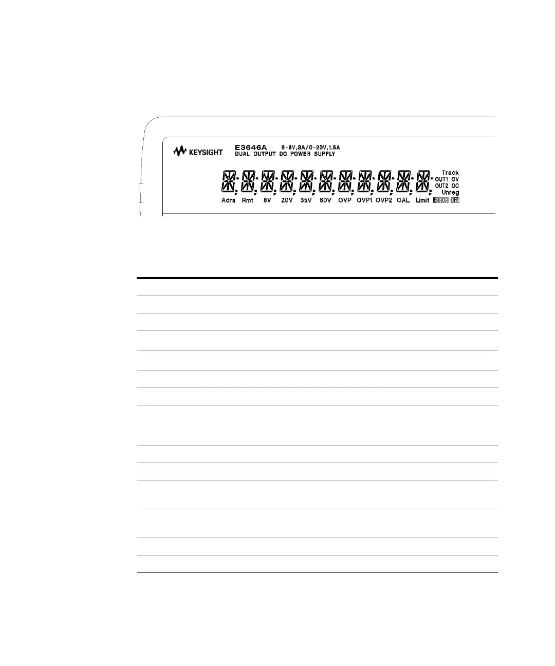
Display annunciators
Figure 1-6 Display annunciators
Table 1-6 Display annunciators overview
Item Description
Adrs The power supply is addressed to listen or talk over a remote interface.
Rmt The power supply is in the remote interface mode.
8V
[a]
/35V
[b]
Indicate that the low voltage range is selected.
20V
[a]
/60V
[b]
Indicate that the high voltage range is selected.
OUT1 The output1 is selected for the front panel or remote operation.
OUT2 The output2 is selected for the front panel or remote operation.
OVP1
The output1 overvoltage protection function is enabled when the OVP1
annunciator turns on or the overvoltage protection circuit has caused the power
supply to shut down when the annunciator blinks.
CAL The power supply is in the calibration mode.
Limit The display shows the limit values of the voltage and current.
ERROR
Hardware or remote interface command errors are detected and the error bit
has not been cleared.
OFF
The output of the power supply is disabled. Refer to “Disabling the Output” on
page 75 for more information.
Unreg The output of the power supply is unregulated (output is neither CV nor CC).
CV The power supply is in the constant voltage mode.