1Introduction
14 Keysight J7211A/B/C Operating and Service Manual
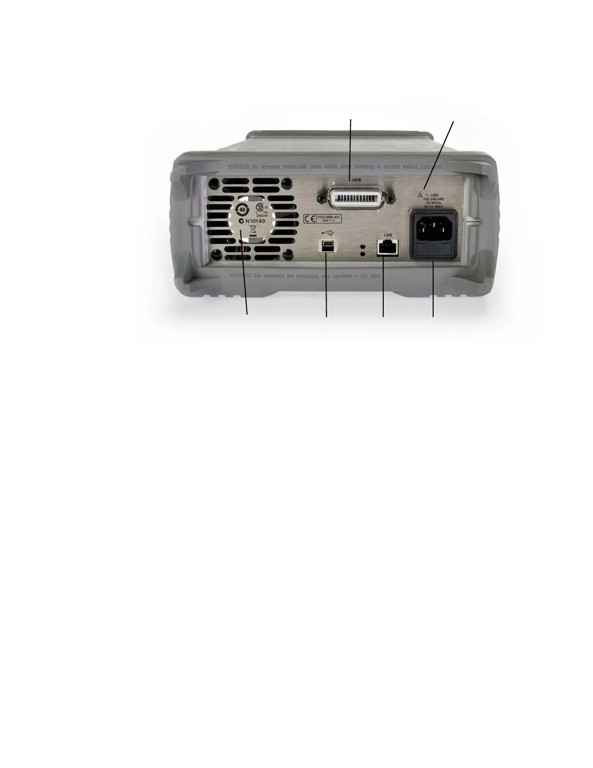
This section briefly describes the function of the rear panel connectors of J7211A/B/C.
Figure 1-2 J7211A/B/C rear panel features
1GPIB connector. The interface connector from a source device to a listening device for remote
mode of operation.
2Alert symbol. This symbol is used to point out a necessary reference for the user.
3 Receptacle. Matches transformer primary to line voltage via power cable.
4 LAN connector. The interface connector for LAN cable.
5 USB connector. The interface connector for Type mini B 5—pin USB cable.
6 Instrument Markings.
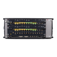
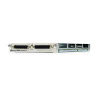
Types of RF connectors for J7211A/B/C
Below illustrations are the RF connectors’ selections for J7211A/B/C.