Keysight CXG, EXG, and MXG X-Series Signal Generators Service Guide 205
RF Assembly
A3 RF Assembly Troubleshooting
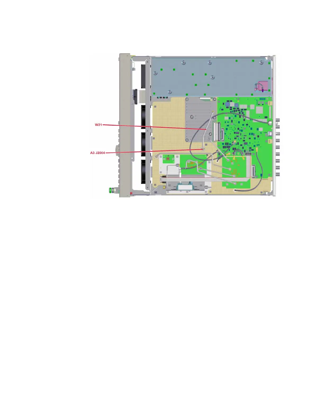
Figure 10-4 Synthesizer Multiplier / Divider Section Output - Microwave
4. Tune the instrument to a frequency that exhibits the power level issue.
5. Connect a spectrum analyzer to A3 J2004.
6. Calculate the Synthesizer Multiplier / Divider output frequency by dividing
the frequency of the signal source output by the corresponding A7
Multiplier listed in Table 10-5.
7. Configure the spectrum analyzer with the following settings:
— Center Frequency = Frequency calculated in step 6
— Span = 10 MHz
— Reference Level = +10 dBm
8. The power level of the signal at A3 J2004 should be at a fixed level of 0
dBm, +/-6dB.
— If the power level measured is not 0 dBm, +/-6 dBm, replace the A3
RF assembly since there are no adjustments for this power level.
— If the power level measured is 0 dBm, +/-6 dB, the power level at
the output of the Synthesizer Multiplier / Divider section is correct.
The issue is somewhere farther down the signal path.
 Loading...


