248 Keysight CXG, EXG, and MXG X-Series Signal Generators Service Guide
Baseband Generators
A2 Vector BBG Assembly Troubleshooting
RF Signal Path Level Issues
The troubleshooting information in this section is assuming that there is no
problem with the RF power level when not using digital modulation, the
problem only exists when digital modulation is turned on. If this is not the case,
resolve any power level issue with the digital modulation turned off before
continuing with this procedure.
If the instrument is having a problem with the RF signal path when using digital
modulation, it will need to be determined whether the problem is with the A2
Vector BBG assembly, the A3 RF assembly, or with an adjustment that is
needed. Before performing any troubleshooting for an issue such as this,
restore the calibration data to the factory values in case there is any
overwriting data in the A5 CPU assembly. See the “Calibration Data Restore”
section in Chapter 3, “Instrument Information and Calibration Data,” for
instructions on how to do this.
To isolate a power level issue when using digital modulation use the following
procedure, which will require the use of a spectrum analyzer:
1. Return the instrument to a known state by pressing Preset.
2. Turn both the output power and modulation on by pressing RF On/Off and
Mod On/Off so that the LEDs below them come on.
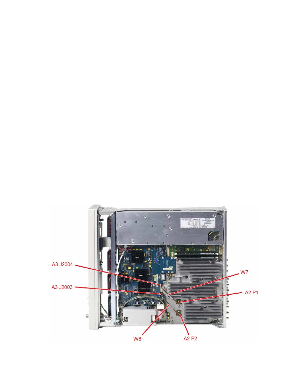
3. Referring to Figure 12-3, remove semi-rigid cable W7.
Figure 12-3 A2 Vector BBG RF Signal Path Connections
 Loading...


