256 Keysight CXG, EXG, and MXG X-Series Signal Generators Service Guide
Baseband Generators
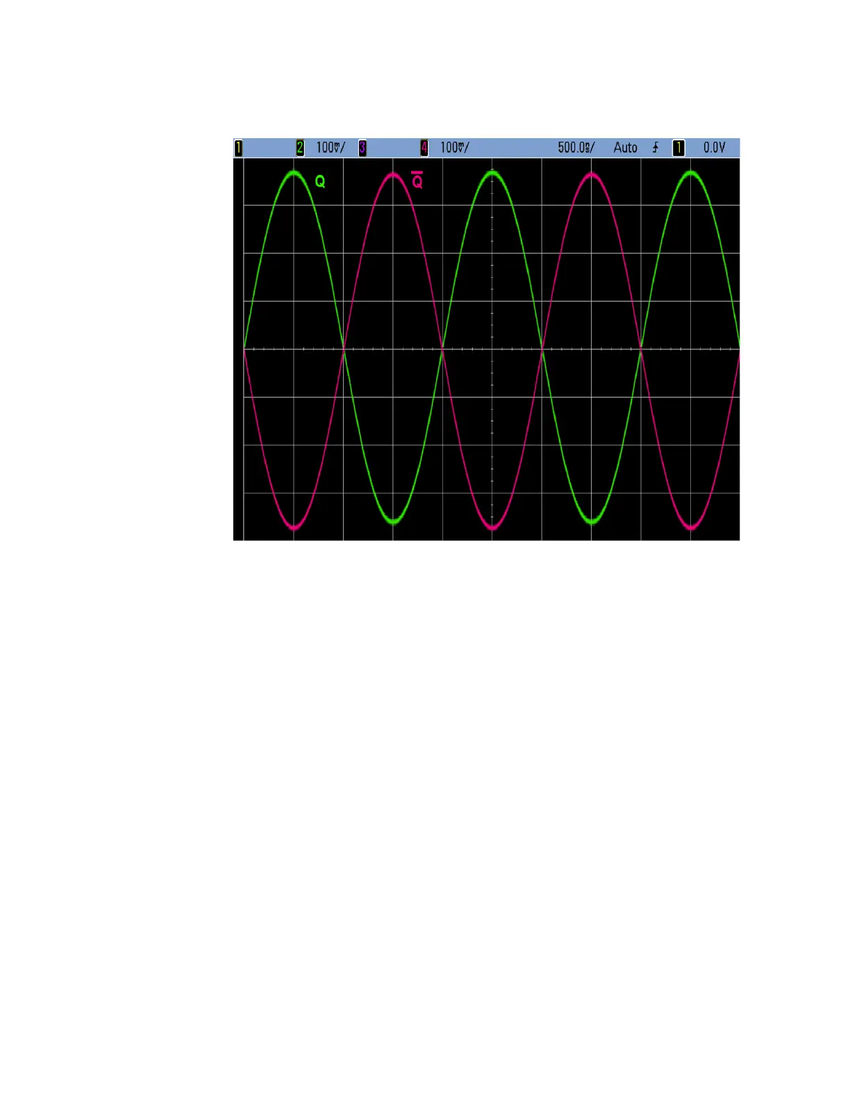
A2 Vector BBG Assembly Troubleshooting
Figure 12-8 Q OUT versus Q Bar OUT
11.If any of the signals do not look like that shown, replace the A2 Vector
BBG assembly.
BB TRIG 1, BB TRIG 2, EVENT 1, PAT TRIG
All four of these connectors can be used as either an input or an output, so the
functionality of both will need to be verified.
Inputs
The following procedure will gate the playing of a waveform with the square
wave output of a function generator applied to each of the four BNC
connectors, one at a time. This will verify that each is functioning as an input.
This procedure will require the use of a function generator and a spectrum
analyzer.
1. Return the instrument to a known state by pressing Preset.
2. Connect the source RF output to the input of a spectrum analyzer.
3. Setup the spectrum analyzer with the following settings:
— Center frequency = 1 GHz
— Span = 100 MHz
— Reference level = 0 dBm
 Loading...


