186 Keysight CXG, EXG, and MXG X-Series Signal Generators Service Guide
RF Assembly
A3 RF Assembly Overview
A3 RF Assembly Overview
Refer to Chapter 13, “Block Diagrams,” for a visual description of the major
blocks of circuitry contained in the A3 RF assembly.
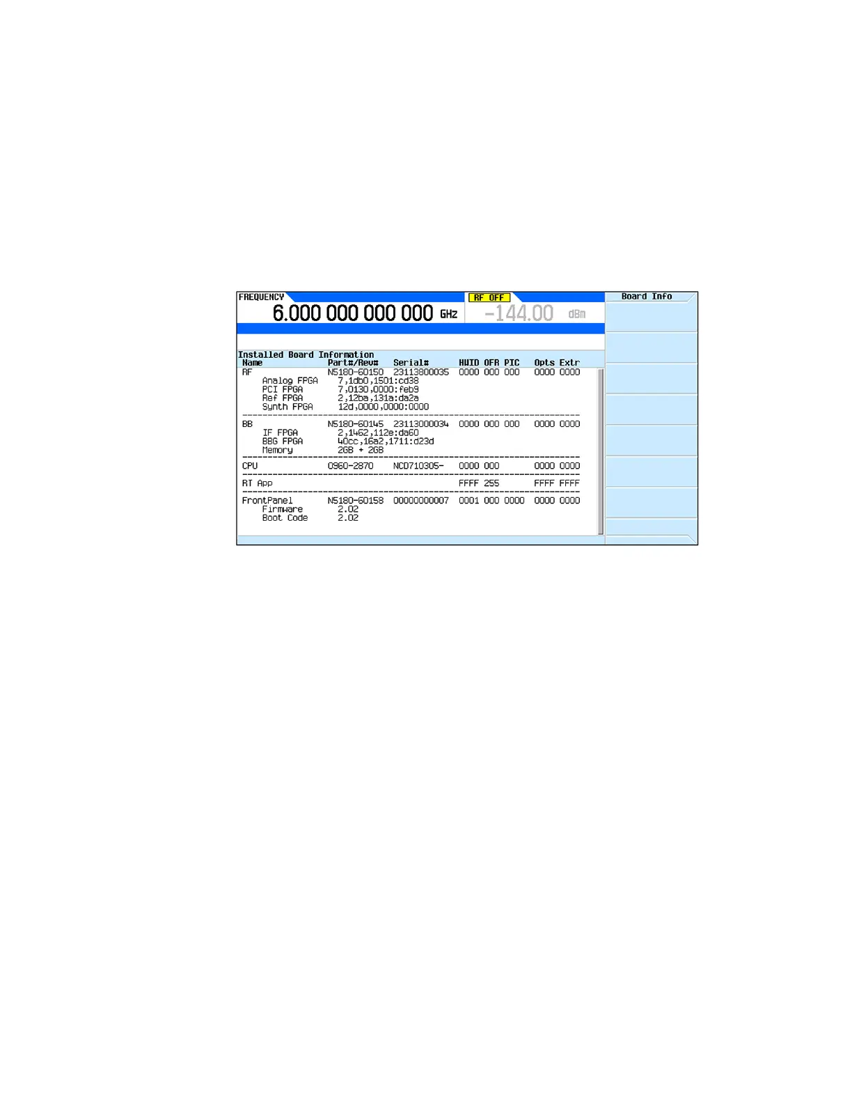
The part number and serial number of the A3 RF assembly installed in an
instrument can be seen on the Utility, Instrument Info, Installed Board Info
screen, as shown in Figure 10-1.
Figure 10-1 Installed Board Info Screen
The A3 RF assembly is made up of eight major sections that will be covered in
this chapter. They are:
— Reference
— Synthesizer
— Synthesizer Multiplier / Divider
—RF Output
— Automatic Level Control
— Function Generator / Trigger Control
—Instrument Interface
— Rear Panel BNC Input / Output
There are five different variations of the A3 RF assembly. They are for:
— CXG RF Instruments (N5166B)
— EXG RF Instruments (N5171B, N5172B)
— MXG RF Instruments (N5181B, N5182B)
— EXG Microwave Instruments (N5173B)
— MXG Microwave Instruments (N5183B)
 Loading...


