40 Keysight CXG, EXG, and MXG X-Series Signal Generators Service Guide
Boot Up and Initialization
Potential Problems During Boot Process
Yellow Standby Front Panel LED is Not Working
The yellow standby LED is controlled by the +5.1 VDC standby line. The +5.1
VDC standby line is supplied by the A1 Power Supply and is routed through the
A3 RF assembly to the front panel through ribbon cable W1. With the
instrument plugged in to an AC power source and the power turned off, the
yellow standby LED should be on. When the instrument is turned on, the
yellow standby LED should turn off and the green front panel power on LED
should turn on. If the yellow standby LED is not functioning as expected, follow
the procedure below to identify the problem.
1. The Standby LED will only turn on when the instrument is connected to an
AC power source that has a voltage level and frequency of that specified
for the instrument. Before proceeding verify that these requirements are
being met. Refer to the instrument rear panel for these requirements.
2. Remove the AC power cord and then remove the instrument outer and
inner bottom covers. Refer to Chapter 15, “Assembly Replacement” of this
manual.
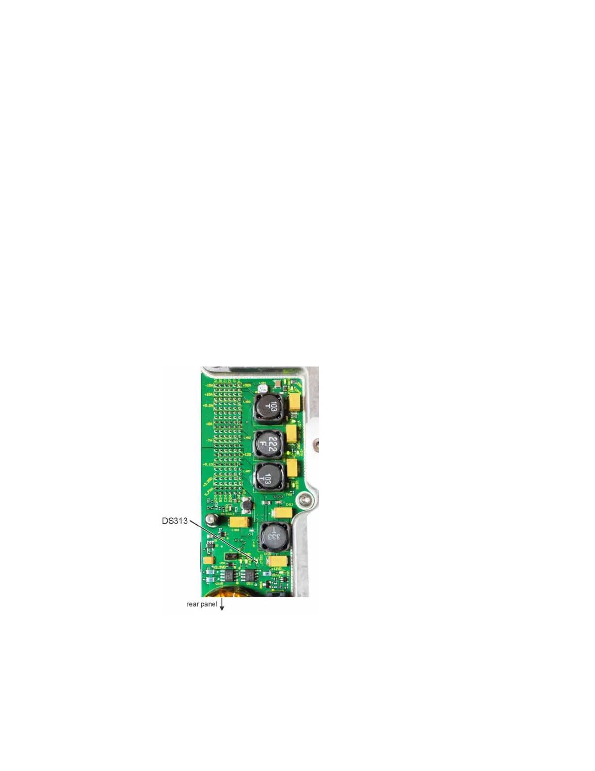
3. Referring to Figure 2-1, verify the +5.1 VSB LED on the A3 RF assembly is
on (green).
Figure 2-1 DS313 +5.1 VSB LED (Standby)
Is DS313 on (green)?
a. If DS313 is on proceed to step 4.
b. If DS313 is not on go to Chapter 8, “Power Supply” to determine
why the +5.1 VSB is not turning on.
 Loading...


