Keysight CXG, EXG, and MXG X-Series Signal Generators Service Guide 41
Boot Up and Initialization
Potential Problems During Boot Process
4. Remove the 4 screws attaching the front frame assembly to the chassis
and tilt it down so that you have access to the rear of the A6A1 Front Panel
Interface board assembly.
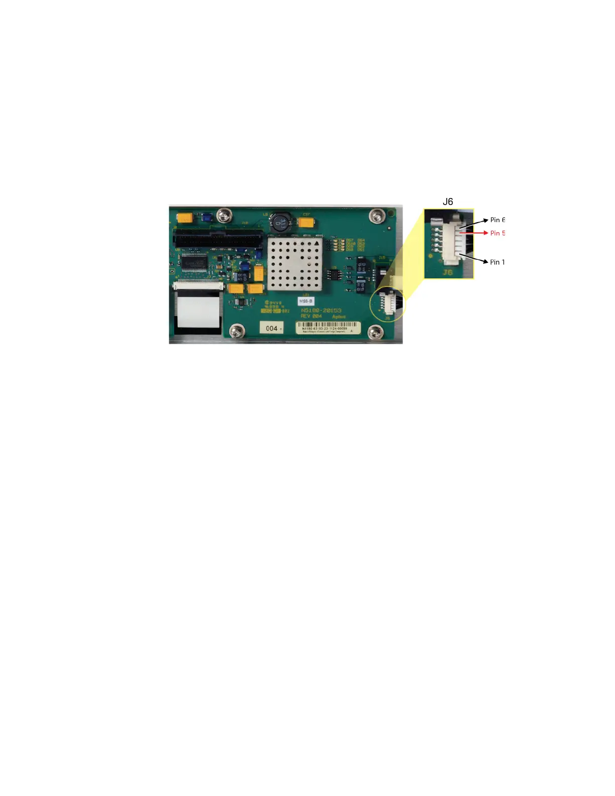
5. Referring to Figure 2-2, verify the standby LED drive voltage on pin 5 of J6
on the A6A1 Front Panel Interface board measures approximately +2.1
VDC.
Figure 2-2 A6A1 Front Panel Interface J6 Pinout
Is the voltage on pin 5 of J6 +2.1 VDC ±0.3 V?
a. If yes, the problem is most likely the A6A3 Power Switch Assembly.
b. If not, the problem is most likely the A6A1 Front Panel Interface
assembly or the W1 Ribbon Cable from the A3 RF Assembly to the
A6A1 Front Panel Interface assembly.
 Loading...


