246 Keysight CXG, EXG, and MXG X-Series Signal Generators Service Guide
Baseband Generators
A2 Vector BBG Assembly Troubleshooting
A2 Vector BBG Assembly Troubleshooting
A2 Vector BBG assembly faults could manifest themselves in a broad range of
failure symptoms. This section will address the most common failure
symptoms.
To provide access to the internal circuitry required to perform the
troubleshooting procedures in this section the instrument outer cover and
inner top cover will first need to be removed. Refer to Chapter 15, “Assembly
Replacement,” for instructions on how to remove and reinstall these covers.
The troubleshooting information in this section is assuming that there are no
error messages referring to any problems with the frequency reference or
synthesizer sections on the A3 RF assembly. If there are any 508 Synthesizer
Unlock, 512 Reference Unlock, or 515 Reference Missing error messages
resolve them before continuing with this procedure.
Before replacing the A2 Vector BBG assembly be sure to see the “Pre Repair
Procedures” section in Chapter 16, “Pre and Post-Repair Procedures”
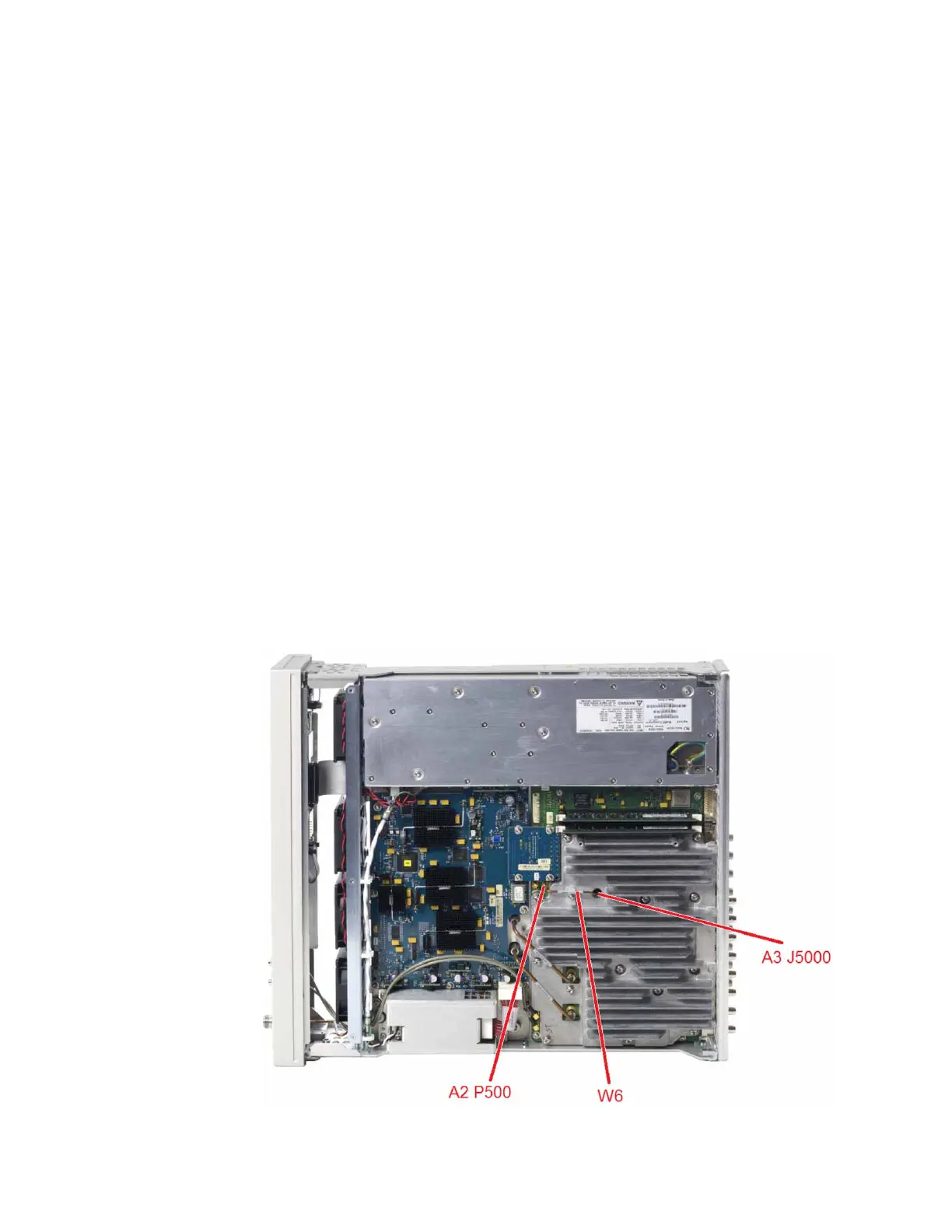
100 MHz Reference Signal
The A2 Vector BBG assembly requires a 100 MHz reference signal from the A3
RF assembly. This signal is provided by cable W6, which connects A3 J5000 to
A2 P500, as shown in Figure 12-2.
Figure 12-2 100 MHz Reference Signal Connections
 Loading...


