Keysight CXG, EXG, and MXG X-Series Signal Generators Service Guide 361
Assembly Replacement
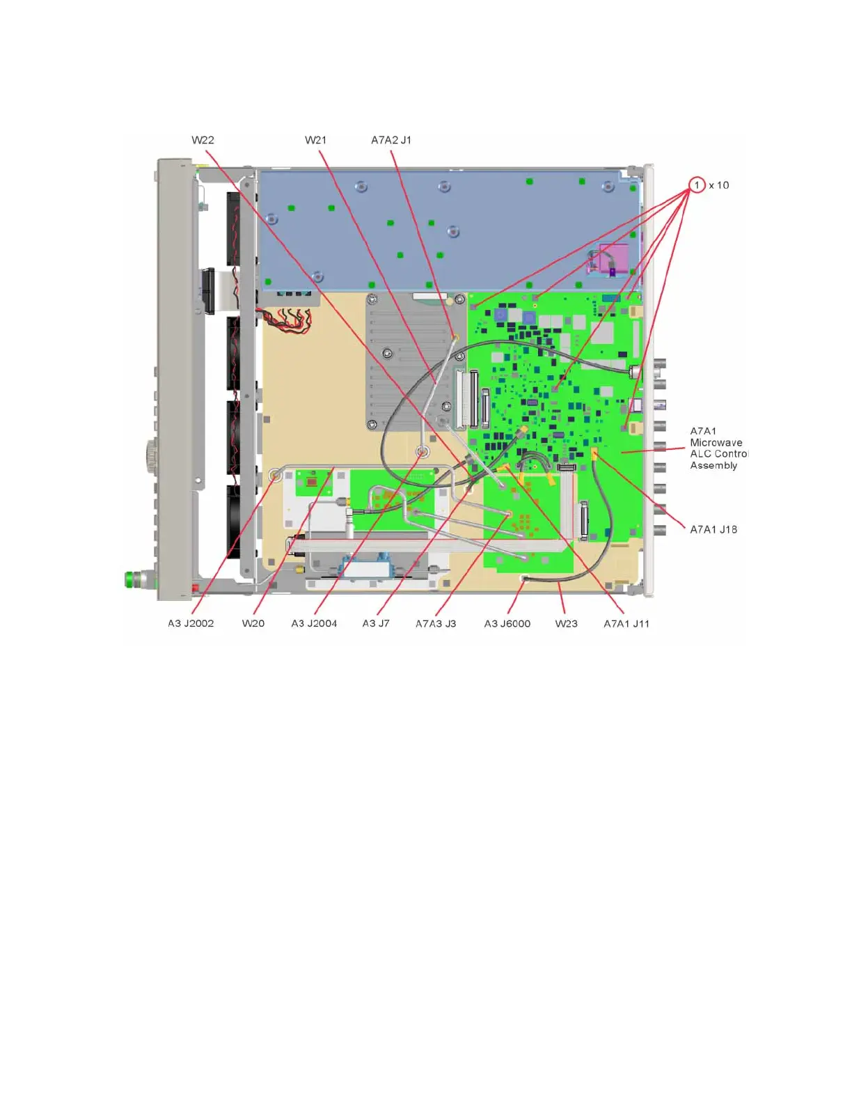
A3 RF Assembly (N5173B, N5183B)
Figure 15-15 A7 Micro-Deck to A3 RF Assembly Interconnections
9. Refer to Figure 15-8. Using the T-10 driver, remove the 10 screws (1) that
connect the A3 RF assembly to the chassis.
10.Refer to Figure 15-10. Place the tip of a medium common screwdriver into
one of the three pry slots on the A3 RF assembly and twist the screwdriver
to release the board from the connector pins.
11.Repeat step 10 with the other two pry slots.
12.Remove the A3 RF assembly as shown in Figure 15-11.
 Loading...


