Repair Guide 6
Keysight N8262A Service Guide 113
Reassembly Instructions
Instructions Visual
– The reassembly process is simply the reverse of
the disassembly process. However, there are
various points to be aware of:
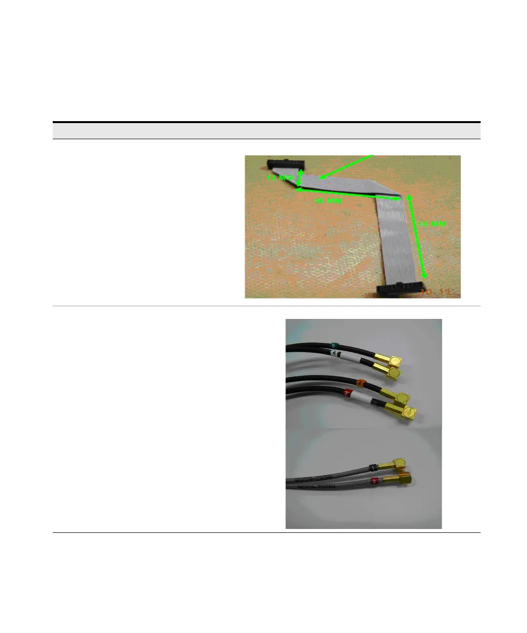
– Make sure the ribbon cable is shaped as in
the figure to the right when you connect a
new front panel board ribbon cable.
– When connecting a new trigger in/out cable
assembly or channel A and B sensor flex cable,
you are recommended to label each of the cable
as follows:
– Channel A top cable labeled with 4
– Channel A bottom cable labeled with 5
– Channel B top cable labeled with 2
– Channel B bottom cable labeled with 3
– Trigger in cable labeled with 1
– Trigger out cable labeled with 2
– See the figure to the right for details.
Channel A and B cable
Trigger in/out cable
 Loading...


