426 Keysight N9927-90001 User’s Guide
Channel Scanner (Option 312)
How to Set Up Channel Scanner
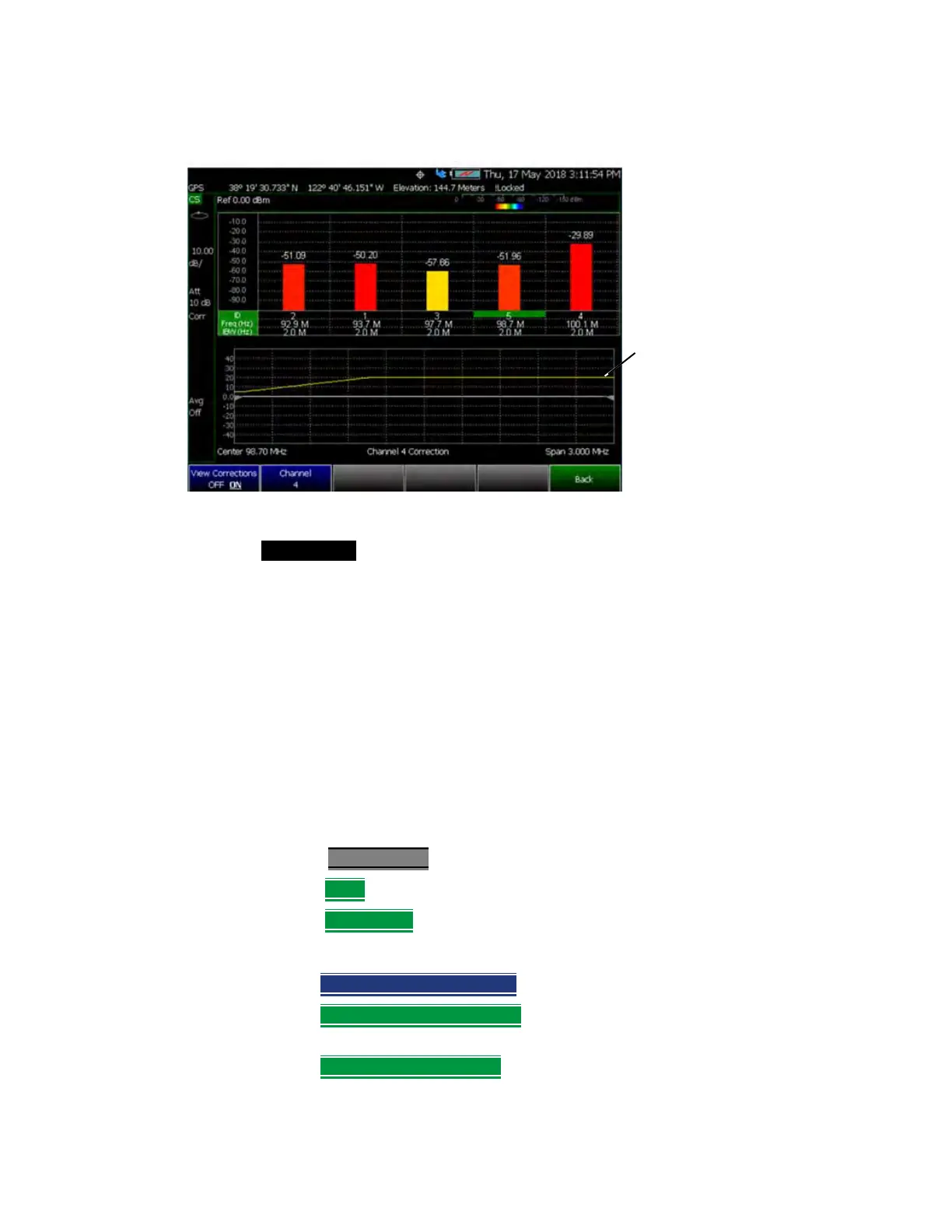
Figure 23-16 Yellow Trace with Cable and Antenna Corrections
Field Strength Measurements
Yellow Trace - Corrected trace with antenna factor. This correction, includes
the sum of the antenna correction and the cable correction (These corrections
are linearly interpolated). (Antenna = ON, Apply Corr = ON). Refer to Figure
23-16 on page 426.
For information, refer to “Trace Display States (SA Mode)” on page 178
— Learn how to set Y-Axis Units on “How to Set Y-axis Units” on page 154.
— Use a Band Power marker to measure total power over a range of
frequencies. Learn how in “Band/Interval Power Marker” on page 190
How to select and edit corrections for Field Strength measurements
The Antenna and Cable correction data survives a Mode Preset and Preset.
All Correction ON/OFF states survive a Mode Preset, but NOT a Preset.
—Press Scale/Amptd
.
—Then More
—Then Corrections
— Then choose from the following:
—Apply Corrections ON OFF
Turn ON and OFF correction for all settings.
—RcvrSide Antenna Off / On
Edit/Recall an Antenna file to be used on
the receiver side.
—RcvrSide Cable Off / On
Edit/Recall a Cable file to be used on the
Receiver side.
Yellow trace:
Cable correction,
which is the sum
of the antenna
correction and
the cable
correction (These
corrections are
linearly
interpolated).