M8100 Series Arbitrary Waveform Generators Getting Started Guide 47
Basic Setup for M8100A 2
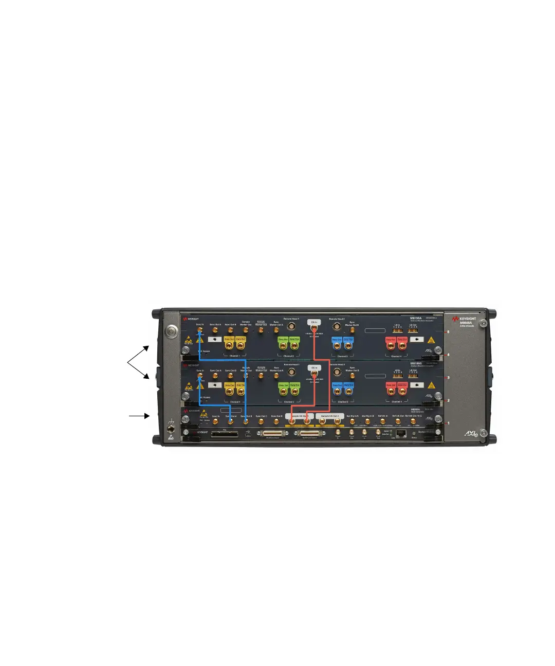
Case 3 Connecting M8008A clock module to two M8199A AWG modules
In this case, a M8008A clock module, two M8199A AWG modules, a
M9505A AXIe chassis and the following cables are required:
• 3.5 mm, 50 cm M8199A-811 customer orderable sync cable
(M8199-61620)
• 1.85 mm, 45 cm M8199A-810 replacement channel clock cable
(M8199-61624)
Make the connections as described below:
1 Connect the M8008A Clock Generator Sync Out port with both the
M8199A AWG Sync In ports using the sync cable (blue cable).
2 Connect the M8008A Clock Generator Sample Clock Out port with
both the M8199A AWG Clock In ports using clock cable (red cable).
Figure 18 shows how to connect M8008A clock generator module to the
two M8199A AWG modules:
Figure 18 Connecting M8008A clock generator to two M8199A AWG modules