Keysight NFA Series Noise Figure Analyzers Service Guide 243
Front End Control Troubleshooting
A15 Front End Control Assembly Troubleshooting
Low Band Switch Control Logic Verification (N8974B, 75B)
Press Mode Preset on the analyzer. Press MODE/MEAS, Spectrum Analyzer,
OK, FREQ, 50 MHz, Span, 2 MHz on the analyzer. Make sure the auto
alignments are turned off by pressing System, Alignments, Auto Align, Auto
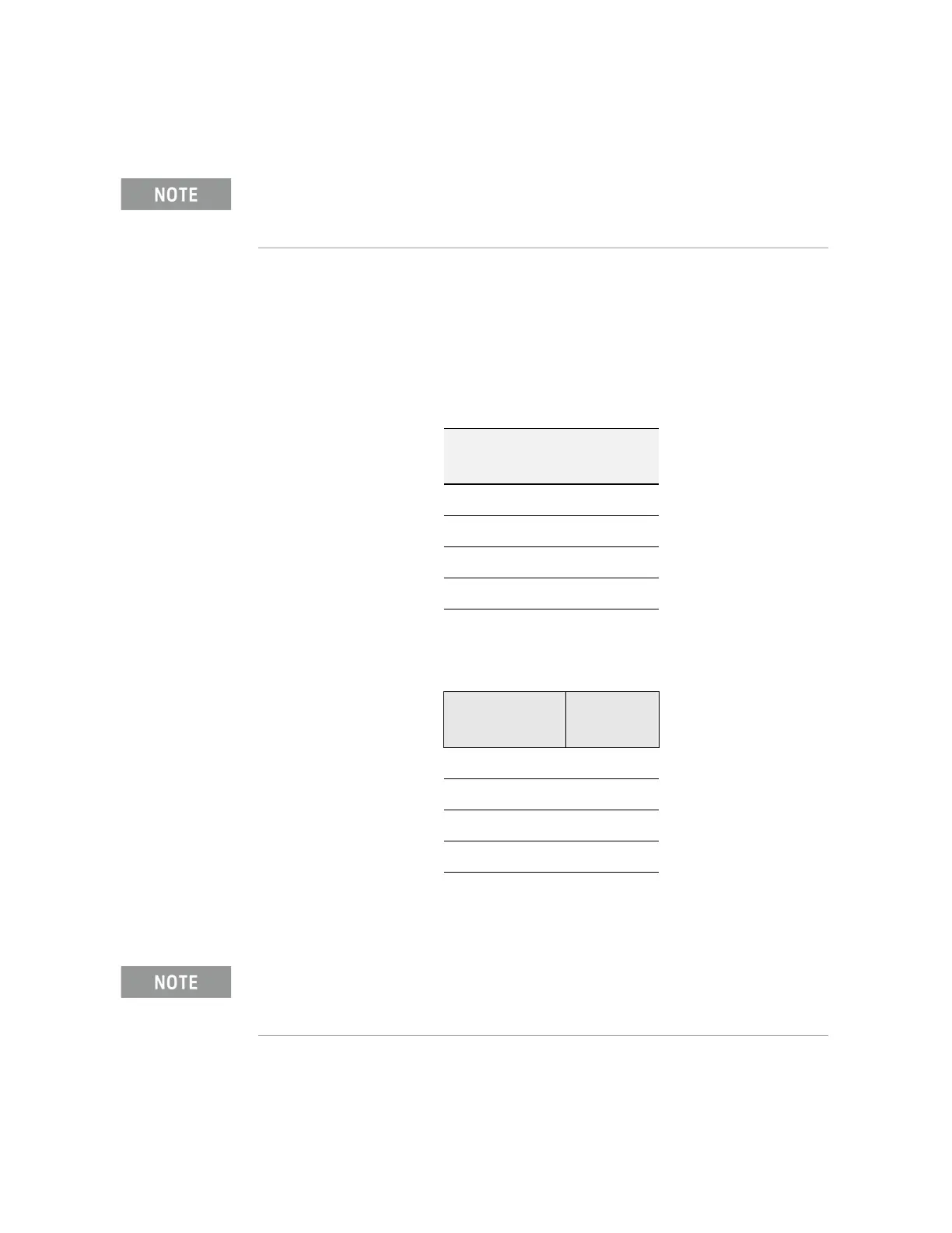
Align, Off. Connect the voltmeter positive lead to test point listed in the table
below and the negative lead to the instrument chassis. These test points are
located under the J2 connector. Verify the voltages in Table 6-8.
Press FREQ, 5 GHz on the analyzer. Verify the voltages in Table 6-9.
If the voltages are not correct, the most probable cause is the A15 Front End
Control board.
If the analyzer is an N8976B, skip to “Disconnect RF Front End Troubleshooting Board”
on page 244.
Table 6-8
Test Board
Test Point
Voltage
(VDC)
In1A −9.90
In2A −9.90
In1B +10.0
In2B +10.0
Table 6-9
Test Board
Test Point
Voltage
(VDC)
In1A +10.0
In2A −9.90
In1B −10.0
In2B +10.0
The procedure above will not work on the N8976B.