Keysight NFA Series Noise Figure Analyzers Service Guide 257
Analog/Digital IF Troubleshooting
25 MHz BW IF Section
9. Connect the W13 cable to the MMCX female to SMA female connector.
Use an appropriate cable to go from the SMA connector to the RF input of
a functioning spectrum analyzer to verify the 22.5 MHz I.F. and amplitude
is correct.
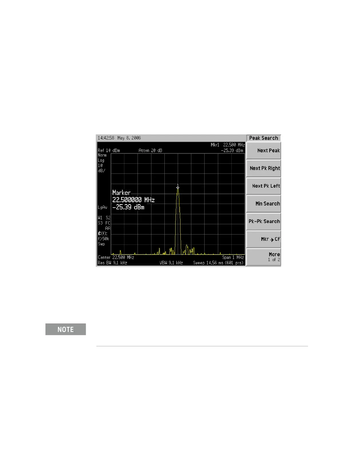
10.Press Freq, 22.5 MHz, Span, 1 MHz, Peak Search on the functioning
spectrum analyzer.
11.The analyzer marker should read 22.5 MHz at −25 dBm ± 4 dBm as shown
in Figure 7-4.
Figure 7-4 A2 Analog I.F. Output
If the 22.5 MHz signal is not measuring the correct power level, do not assume
the Analog I.F. is the most probable cause until the 3rd L.O. frequency and
power level have been verified below.
If the 22.5 MHz signal is within tolerance, carefully reconnect the W13 cable.
You should hear a distinct snap when reconnecting the W13 cable. If this
cable is not installed properly, intermittent signal fluctuations may occur
on the analyzer display.