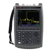
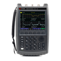
Overview
Front Panel Overview
6
9 Data Control Keys includes the numeric keypad, ENTER key
and backspace key, change the numeric value of an active
function such as center frequency, start frequency, resolution
bandwidth, and marker position.
10 RF IN connector is the signal input for the analyzer. The
maximum damage level is average continuous power
+40 dBm, DC voltage 50 VDC or max pulse voltage 125 V.
The impedance is 50 W. (N- type female).
11 PROBE POWER connector provides power for high- impedance
AC probes or other accessories (+15 V, –12 V, 150 mA
maximum).
12 CAL OUT connector provides an amplitude reference signal
output of 50 MHz at –10 dBm (BNC female).
13 TG SOURCE connector N- type female, is the source output for
the built- in tracking generator. The impedance is 50 W. (for
Option TG3)
14 Standby Switch switches on all functions of the analyzer. To
switch the analyzer off, press the switch for at least 2
seconds. This deactivates all the functions but retains power
to internal circuits so long as the analyzer is connected to
line power.
15 On LED (green) lights when the analyzer is switched on.
16 Standby LED (orange) lights when the analyzer is connected
to the line power.
17 Remote LED lights when the analyzer is remotely controlled
by a PC via the USB host interface on the rear panel.
18 USB Device Connector provides a connection between external
USB devices and the analyzer, such as a USB memory
device.
CAUTION
If the tracking generator output power is higher than the maximum power
that the device under test can tolerate, it may damage the device under
test. Do not exceed the maximum power of DUT.
 Loading...


