Page 18
Find us at www.keysight.com
Test port 3
C
R3
Test port 1
R1
Test port 4
R4
Test port 2
R2
35 dB
65 dB
35 dB
65 dB 65 dB
35
dB
65 dB
A
35 dB
D B
Source 2
OUT 1OUT 2
Pulse
modulator
Source 1
OUT 1OUT 2
Pulse
modulator
Pulse generators
To receivers
LO
RABCD
IF inputs
Rear panel
4-ports, dual source, with extended power range
and bias-tees (Option 419)
This configuration comes with two sources, front-panel access
loops, and bias tees and source and receiver attenuators
at each port. The source attenuators are settable in 5 dB
steps up to 65 dB in N5221/22B, in 10 dB steps up to 60 dB
in N5224/25B, and in 10 dB steps up to 50 dB in N5227B.
The receiver attenuators are settable in 5 dB steps up to
35 dB in N5221/22/24/25B, and 10 dB steps up to 50 dB in
N5227B. The bias tees are connected directly to the test port
couplers, which limits the maximum power rating on the pair
to +30 dBm (additional attenuators or isolators are typically
required to protect other components inside the instrument).
To independently control the frequency of the second internal
source, one of the following software applications is required:
S93080/029/082/083/084/086/087/089/090x/093/094B/A.
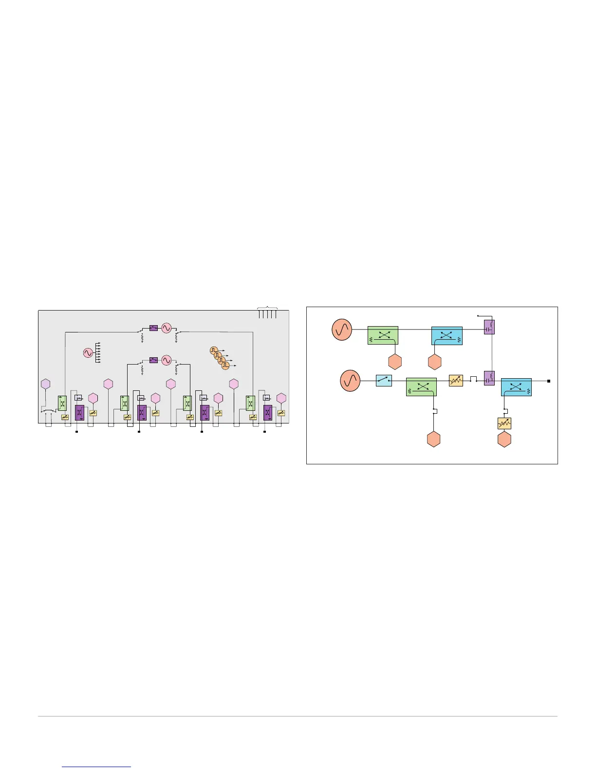
4-ports, dual source, with extended power range,
bias-tees, and low-frequency extension (Option
420)
4-ports, dual source, with extended power range, bias-tees,
and low-frequency extension (Option 420). Along with the two
sources, front-panel access loops, bias tees, source and receiver
attenuators of Option 419, Option 420 adds additional hardware
to extend the start frequency of the PNA down to 900 Hz. The
extended start frequency is available only for the following
measurement classes: standard, gain compression (amplifier and
converters), and for magnitude-only measurements using SMC
(scalar mixer/converter) or SMC+Phase. In the standard channel,
pulsed RF, true-mode stimulus, and source phase control are not
supported for measurements below 10 MHz. The block diagram
below shows how the low-frequency hardware is configured for
one test port; the other test ports are configured similarly.
Standard source
10 MHz - 8.5/13.5/26.5/43.5/50/67.5 GHz
Pulse modulator
R1
A
Test
port
A'
LF source
900 Hz - 100 MHz
R1'
External bias
1. The block diagrams shown above include hardware that must be ordered
as separate options, such as pulse modulators (Options 021 and 022),
and IF access (Option 020), or is controlled by application software, as
is the case for the pulse generators. In addition, the combiner type and
attenuator values vary by model number. Refer to the product data sheet
for the correct block diagram for a specific model.
PNA Series Test Set and Power Configuration Options
1
(Continued)

 Loading...


