6 U9361C/F/G/M RCal Measurement Guide
Getting Started
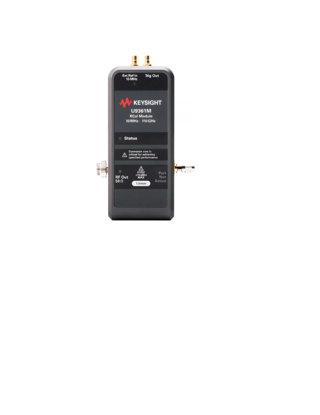
RCal I/O
RCal I/O
The typical RCal use case requires three connections: USB Power & Control,
Ext Ref In, and RF Out.
USB Power & Control
RCal has a USB Type-C connector, which must be connected to the signal
analyzer for both power and control. Since RCal needs ample current to
operate correctly, be sure to use one of the following ports:
— The signal analyzer front-panel USB 2.0 port, marked with a lightning bolt
symbol (bottom front panel USB connector closest to RF input connector)
or marked in blue (for the N9042B).
— A signal analyzer rear-panel USB 3.0 port, identified with “SS” or having a
blue connector.
When plugged in, the RCal module will boot up, accompanied by an LED boot
sequence. When boot-up is complete, the LEDs will settle to Status = Green.
For more information about RCal’s LED codes, see “LED Indicators on RCal
Module” on page 8.