KIC 2000 v2.4.0.x
58 KIC 2000 User Manual
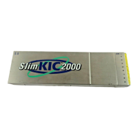
Connecting the Air TC
The next screen shows directions for attaching the Air
TC to your product. It is important to follow these
instructions. See Figure 89.
The Air TC starts and stops the profile automatically,
measures the oven, and provides useful profile
information.
In certain processes it may be beneficial to wrap the end
of the Air TC with tape to give it more surface area.
KIC recommends wrapping the Air TC when profiling:
• Wave Solder.
• Anytime IR heat is present.
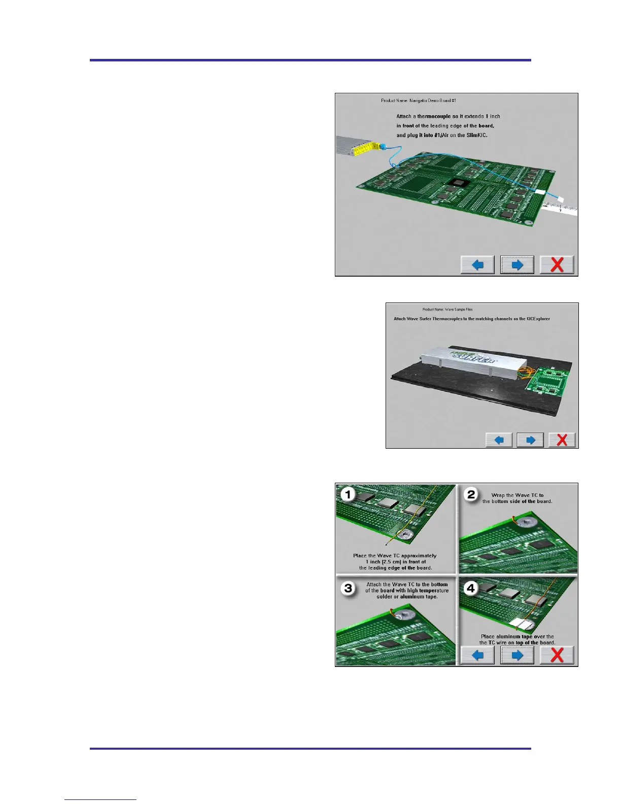
Wave Surfer
Wave Surfer users connect the designated
thermocouples to the corresponding channels on the
SlimKIC 2000.
Make sure the retainers holding the SlimKIC 2000 are
in place and secure. See Figure 90.
If any of the embedded thermocouples are damaged or show signs of
wear replace them.
In addition to the instructions given, it is very important that you
position the “Air TC” so that it touches the wave(s). The “Air TC
must pass through the wave in order to provide accurate profile
results. Of course it you are profiling a Wave Solder machine with
the wave off, the Air TC position is not critical to the profile results.
Select the Forward Arrow button to continue.
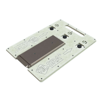
Connecting Wave TC’s
The next screen will depict thermocouple attachment for
wave solder profiling with the wave on. The KIC 2000
software utilizes two Wave TC’s in addition to the Air
TC to collect wave specific data. See Figure 91.
One Wave TC is placed on the Right side of the board
and one on the Left side near the leading edge of the
profile board.
KIC recommend using high temperature solder to
connect both Wave TC’s.
The wave TC’s will measure -Wave Dwell time and
Parallelism when profiling a wave solder machine with
the wave on.
Select the Forward Arrow button to continue.
Figure 89: Run a Profile Screen #4 – No Wave Surfer
Figure 90: Run a Profile Screen #4 – Wave Surfer
Figure 91: Run a Profile Screen #5