SRA Smart Reflow Analyzer Hardware Guide SRA-330200-000
22
Remove SRA Module
1. Open the thermal shield cover, locate and remove the four (4) M3
mounting screws.
2. Lift the SRA module slightly out of the shield and then unplug the
two (2) connectors at the front edge of the module. This allows
the module to be taken completely out of the main assembly.
Establish communication
3. Connect the SRA module to the computer USB port. (The device should power on automatically when
connected to the PC.)
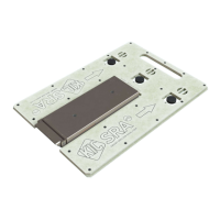
4. Connect the calibration adapter cables to the SRA module, making sure to note the orientation of the
connector. The side of the connectors stamped with the word ‘Top’ should face up. Either connector can
plug into either slot of the SRA module.
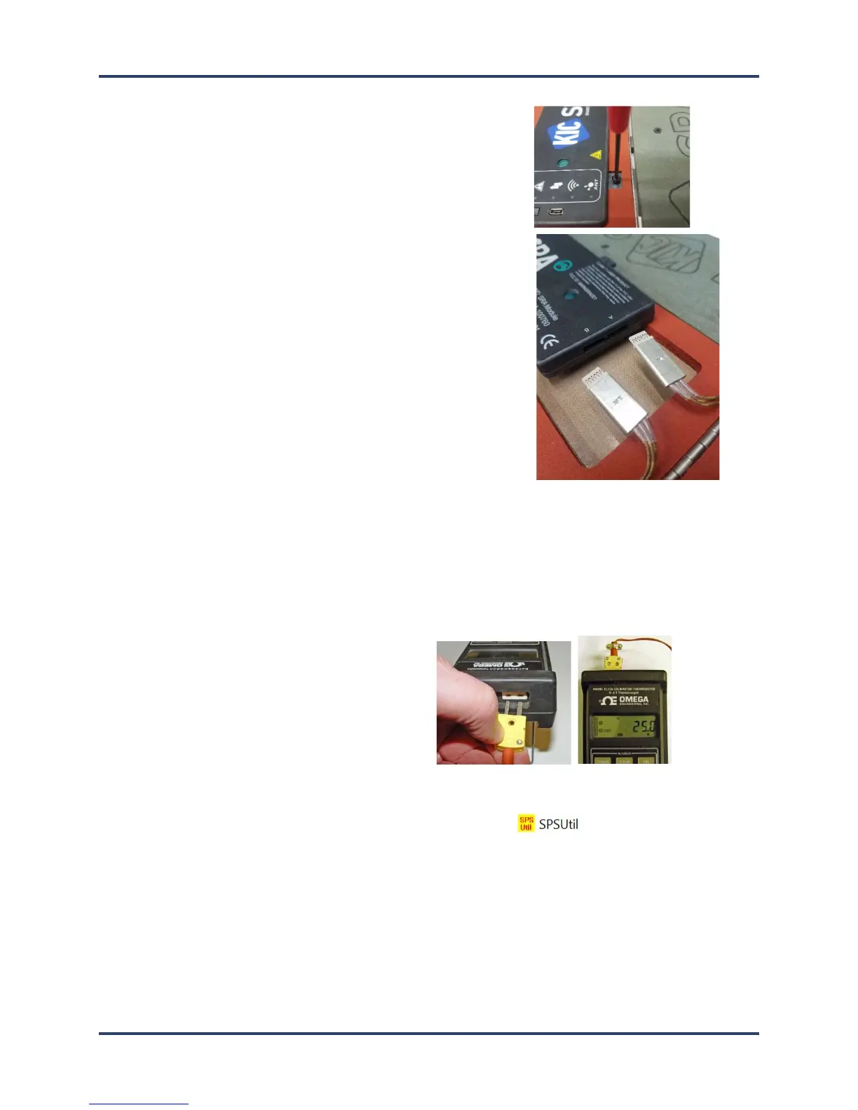
5. Connect the other end of the adapter to the
output port (left side when instrument
viewed upright) of the type K thermocouple
simulator.
6. Turn on the power to the thermocouple simulator, and set the output value to 25°C (77°F).
7. Open the SRA Utility folder and double click the SRA Util icon
(default folder location =
C:\Profiling Software 2G\SPS Utility).