Page 30
Stratos HSSD-2 • INSTALLER’S HANDBOOK • Iss. 12
5.3.2
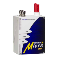
Command Module
terminal block
connections
All electrical (power and signal) connections should be made to the green terminal
block inside the detector. Power cables should be screened and of sufficient current car-
rying capacity. Signal cable should be 120Ω screened twisted pair such as Belden 9841
24AWG. Power and signal cables should enter the detector via metal cable glands.
Terminal block connections are as described below.
* These connections can be used as the input terminals for mains supply and battery
fault sensing. When this is the case, the contacts will signal a fault when the contacts
are open rather than closed, as fault relays operate in the opposite sense to other relays,
i.e. they are held closed during normal operation.
The factory default setting is for supply monitoring on ‘I/P 1’.
†
These connections are used to connect a Command Module to an addressable Fire
Panel when a suitable Universal Addressable Interface card (see section 8.3) is fitted to
the ‘Addressable Interface’ connector on the left hand edge of the Command Module
main PCB.
RS232-2 earth
RS232-2 receive line
RS232-2 transmit line
Spare connection
Remote input 2.
Short pair to activate*
Remote input 1.
Short pair to activate*
N/O Fire 2 contacts
N/O Fire 1 contacts
N/O = Normally open
N/C = Normally closed
N/O Pre-Alarm contacts
N/O Aux contacts
N/C Fault contacts
Addressable bus 2 high o/p
†
Addressable bus 2 low o/p
†
Addressable bus 1 high o/p
†
Addressable bus 1 low o/p
RS485 bus 1 screen
RS485 bus 2 data line A
RS485 bus 2 data line B
RS485 bus 2 screen
RS485 bus 1 data line A
RS485 bus 1 data line B
N/O Fire 2 contacts
N/O Fire 1 contacts
N/O Pre-Alarm contacts
N/O Aux contacts