TM0024 Page 31 of 33 Issue 2.01
CHAPTER 7
ENGINEERS SPECIFICATION
7. ENGINEERS SPECIFICATION
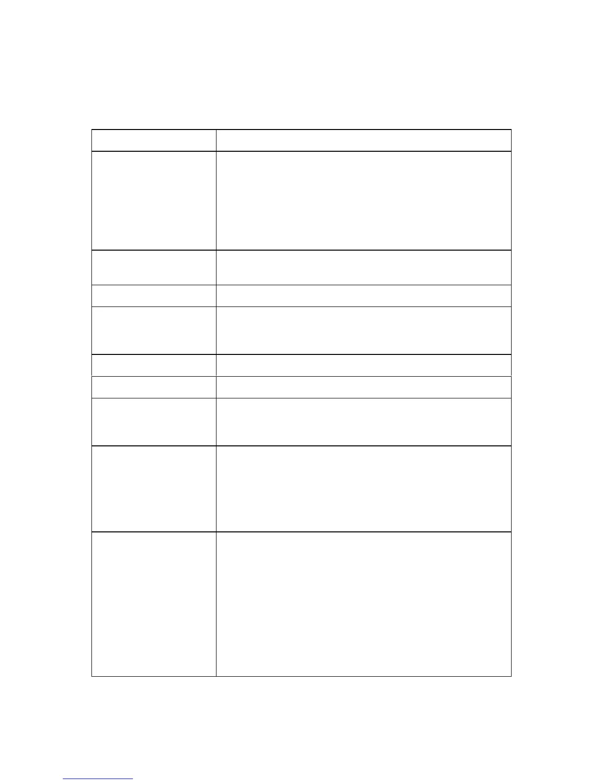
DESCRIPTION
REPEATER
Type 1
Type 2
A maximum of 63 repeaters per main control panel.
Repeater panel without controls over the main panel.
Maximum of 49 allowed each having a common address
of “0".
Repeater panel with controls over the main panel.
Maximum of Total of 15 allowed. Each with its own
unique address (1-15).
DISPLAY 8 line by 40 character Liquid Crystal Display – Backlit.
Viewing adjustable via “R4" on PCB 44782-K077.
INDICATIONS 14 status indications defined by EN54 part 2 (optional).
24 Fire and Fault zone indications. Expandable in blocks
of 32 indications to give the options of 56, 88 and 120
(optional).
64 plant indication (optional).
PRINTER 24 volt dot matrix Fast Action printer (optional).
CURRENT VALUES
LCD only Repeater
LCD c/w 24 zones
Quiescent = 90 mA : Alarm = 120 mA
Quiescent = 120 mA : Alarm = 170 mA
POWER SUPPLY
UNIT
2.5 amp PSU
Battery Charging
Fuse
110 - 270 Volt AC mains input voltage sensing.
Flat - 27.7v @ 2.5 amps ± 0.4 volts DC.
Load shed - 20.4 to 21.4 volts DC. ± 0.4 volts DC.
3.5 amp 20mm ceramic fuse.
DIMENSIONS
Enclosure Finish
Cable Entry
Weight
IP Rating
Battery Capacity
Based upon an LCD Repeater Only (No space for
printer).
250mm High by 500mm wide by 125mm deep.
Semi Gloss Ash Grey - BS4800 00A01 (other colours
optional).
20mm Pre formed knockouts top & bottom.
7.6 Kg - Unpacked (standard enclosure 250x500x125).
10 Kg - Packaged (standard enclosure 250x500x125).
IP31
Space for 2 x 12 volt 3.2 amp per hour SLA batteries.