TM0024 Page 6 of 33 Issue 2.01
1.5 SWITCH CONFIGURATION INFORMATION
The repeater control panels have various sets of internal switches, which will allow
for different operational configurations of the repeaters.
The configuration switches are located on the Repeater Processor card, part number
44782-K077 and is a 4-way switch. Table 1.0 details the information for these
switches.
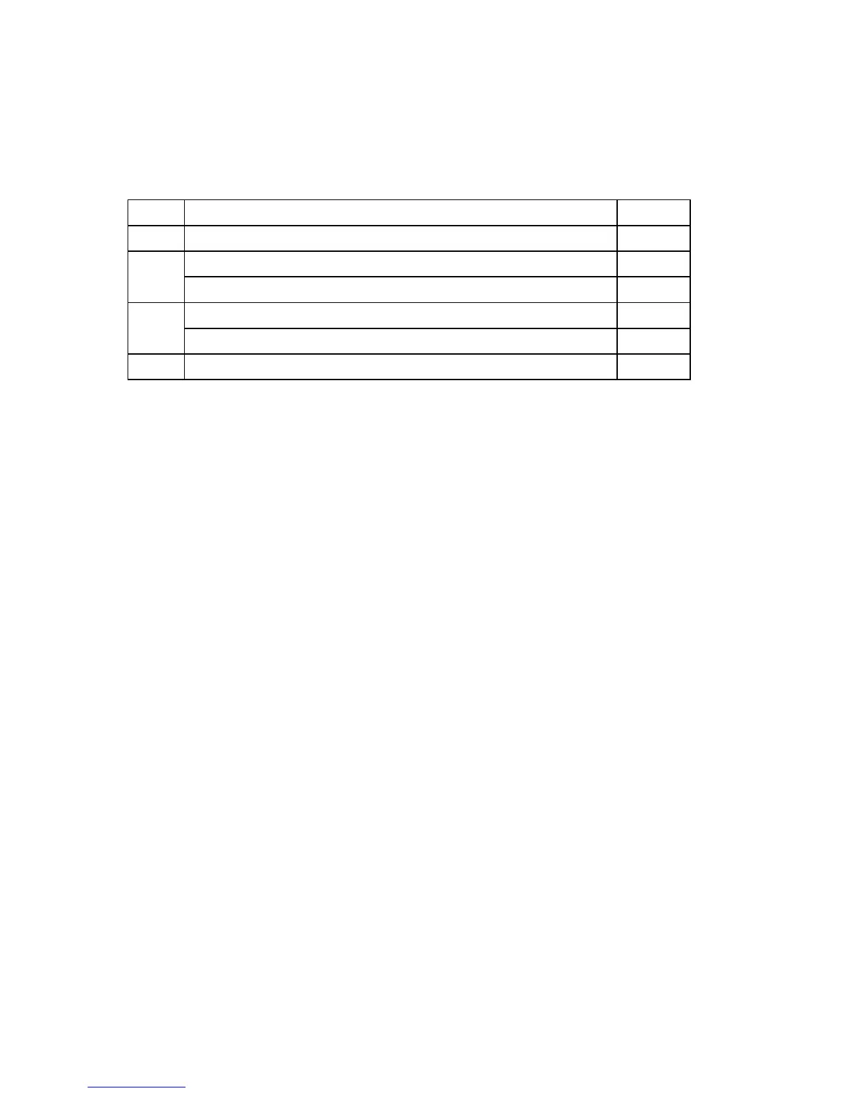
Ref. Switch Description Position
1 Enable Local Printer ON
Deactivation of System Buzzers (Global) OFF
2
Deactivation of Local Buzzer ON
Repeater Backlight Permanently OFF OFF
3
Repeater Backlight Permanently ON ON
4 Deactivation of Local Sounder by use of the “Silence Buzzer” key. ON
Table 1.
The configuration switches are located on the Repeater terminal card, part number
44782-K078 and is a 2 way switch which operate in conjunction with one another.
These switches, when placed in the 'On' position, will install the communications
termination resistor. The termination resistor is only used when the repeater panel is
the very last on the system. These switches will work in conjunction with the switches
located within the main control panel on the Repeater Interface Card, part number
44782-K076.