Notication
Appliances
Hazardous Location
Devices
Door Holders
& Relays
Initiating
Devices
VM Series
Head End
3
VS Series
VM
Head End
SERIES
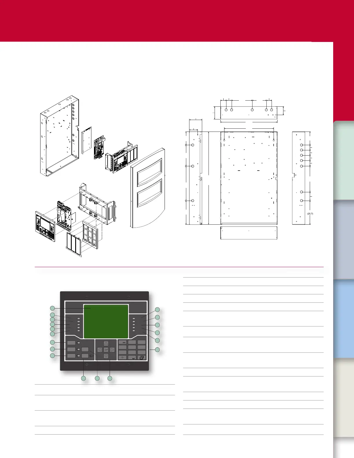
Assembly
VM Series systems are designed for quick assembly and easy ac-
cess in the eld. Components are modular and require no special
tools to service or replace.
Dimensions
The backbox is designed for semiush or surface mounting. Conduit
and nail knockouts, keyhole style mounting holes, and wide wiring
troughs facilitate eciency during installation.
in (cm)
8.2
14.1
21.7
19.0
2.2 2.12.0
7.9
5.4
8.1
5.1
1.9 (4.9)
2.0 (5.1
2.2 (5.5)
10.8
3.3 (8.4)
8.2
3.5
3.5 (8.9)
3.2
(5.5)(5.3) (5.1)
(20.1) (13.7)
(55.2)
(48.3)
(27.5)
2.0 (5.1)
35.5
(90.1)
Top view
Bottom view
Side viewSide view
5.1
(12.9)
(8.2)
3.2 (8.1)
(8.9)
Note: Add 0.25 in (0.64 cm). to height and width dimensions to allow for knockouts
when framing in the backbox for semiush mounting.
CAB6 Backbox
PS10-4B insulator plate
PS10-4B power supply
VM-ELEC Chassis
Electronics
Assembly
VMD Door
(silver or red)
VM-CPU main
board
VM-LCD user
interface
Mounting frame
Filler plates
1
ACK/Panel
Silence
Alarm
Silence
Reset Drill
Details
Power
Test
Ground
Fault
Monitor
Service
Detector
Supervisory
Alarm
Trouble
Disable
CPU Fail
1
4
7
2
5
8
3
6
9
0
BC
JKL
TUV
DEF
MNO
WXYZ
GHI
PQRS
VM
SERIES
2
3
4
5
6
79
12
11
10
8
14
17
13
15
16
18
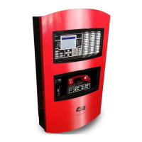
Operation
1 Alarm
Flashing indicates new alarm events. On indicates all
alarm events have been acknowledged.
2 Supervisory
Flashing indicates new supervisory events
On indicates all supervisory events have been
acknowledged.
3 Trouble
Flashing indicates new trouble events.
Steady indicates all trouble events have been
acknowledged.
4 Disable Indicates a system component has been disabled.
5 CPU Fail LED Indicates a CPU process failure.
6 Keypad Includes alphanumeric keys, backspace key, menu key.
7 Cursor controls Includes up, down, left, and right arrow keys, Enter key.
8 Details Displays additional information on the selected event.
9 Drill
Activates audible alarm signals and, if congured,
visible alarm signals. The LED indicates that Drill
operation is active.
10 Reset
Resets the re alarm system.
The LED indicates the panel is resetting.
11
Alarm
Silencebutton/
LED
Silences alarm signals.
The LED indicates that Alarm Silence is active.
12
ACK/Panel
Silence
Silences the panel buzzer and acknowledges all new
events.
The LED indicates that Panel Silence is active.
13 Service Detector Indicates a detector needs servicing
14 Monitor
Flashing indicates new monitor events.
On: Indicates all monitor events have been
acknowledged.
15 Ground Fault Indicates a system ground fault.
16 Test Indicates system components are being tested.
17 Power
On indicates the panel is using primary power.
O iIndicates the panel (or another panel on the
network) is using battery power.
18 LCD
Displays system status, event messages, reports, and
operator menus.