VM Series
Head End
12
SUBMIT
VM
Head End
SERIES
Accessories
12
3
4
56
7
8
1112
16 15 14 13
To earth ground
24 VDC+
24 VDC-
From UL/ULC listed
fire alarm panel [4]
910
3-2-1
LED 1
JP1
LED 2
+
+
-
-
Circuit Pair 1 IN
Circuit Pair 2 IN
+
+
-
-
Circuit Pair 1 OUT
Circuit Pair 2 OUT
+
-
+
-
From IDC or
previous GFD
To next GFD
or EOLR [3] [4]
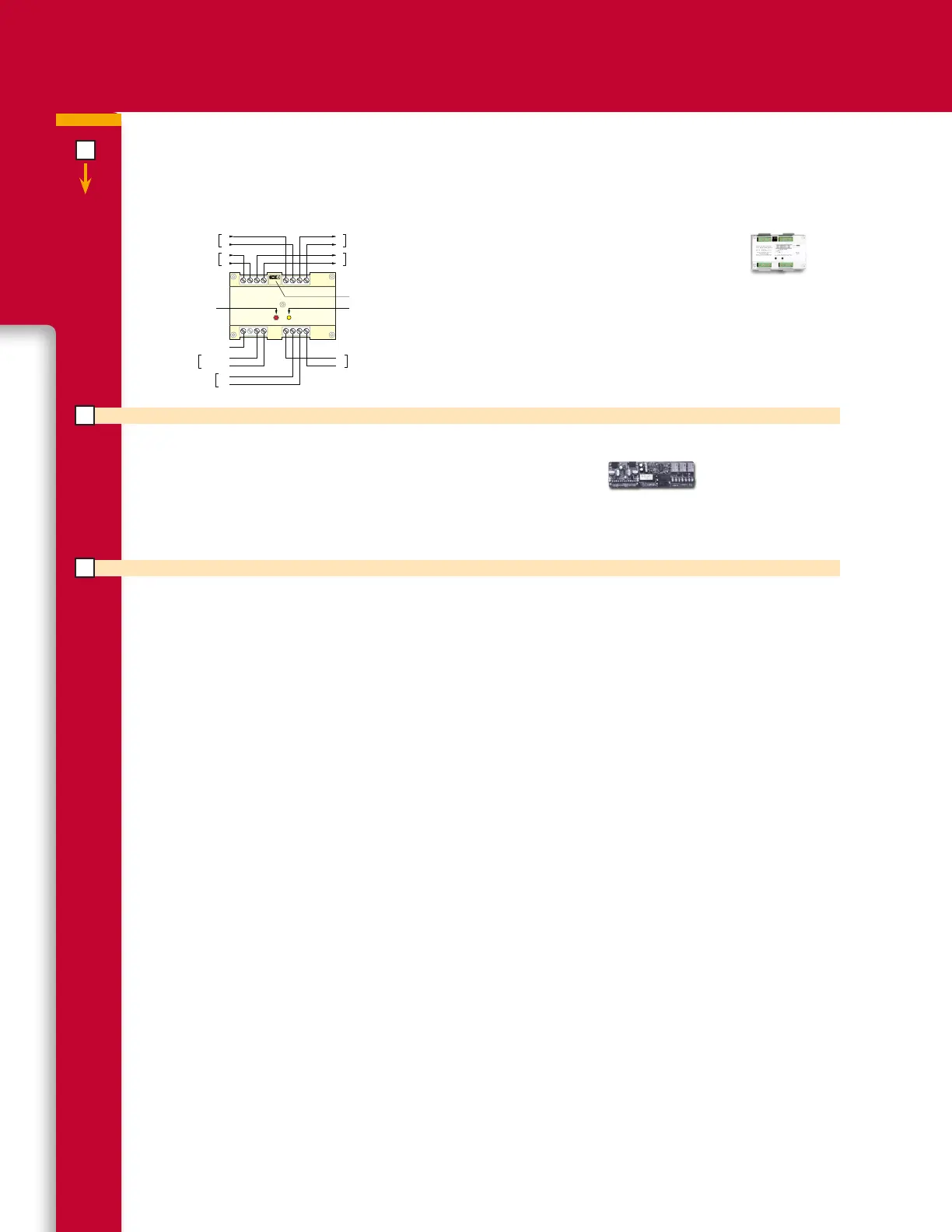
Ground Fault Detection Module
The GFD module is designed to detect ground fault conditions on either
of two independent power or data circuits. Each circuit must be balanced
with respect to ground. The module will detect when the resistance be-
tween any of the monitored conductors and earth ground drops below 10
K Ohms. Two LEDs are provided to indicate the conductor with the ground
condition. A normally energized Trouble/Ground Fault relay is provided with
NO/NC relay contacts for interfacing with monitoring systems.
GFD Ground Fault Detection Module Data Sheet K85010-0115
CDR-3 Coder
The CDR-3 Coder is an auxiliary circuit option module that provides two audio outputs, March Time and PSNI, (Positive,
successive, non-interfering). Dry relay contacts are provided for PSNI code, march time and duration. For the PSNI code,
the RS-232C input provides communications, between VM Series’s RS-232 communications card and the CDR-3.
CDR-3 PSNI Coder Module Data Sheet: K85003-02709