Appendix C: Applications
230 P/N 3102351-EN • REV 005 • ISS 28DEC18
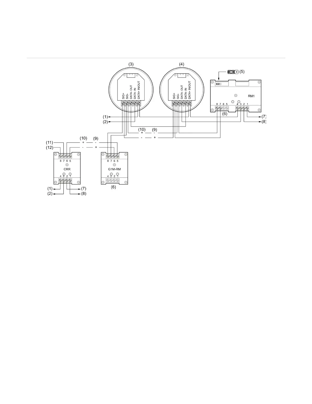
RM1 Riser Monitor module. You can also use a CT1 module and a PAM-1 control relay for this
purpose. In addition a G1M-RM is required for synchronization.
Figure 60: Typical wiring for a system alarm signaling application
SLC IN −
First detector
Last detector
JP1:L 24 VDC monitor
(8) SLC OUT −
(9) Active
(10) Normal
(11) AUX riser 24 VDC +
Notes
• A polarity reversal module can be used to provide power to the sounder bases. You can omit the polarity
reversal module if correlation groups are used to activate the sounder bases.
• The RM1 module is used to monitor riser polarity. You can also use a CT1 module and a PAM-1 control relay
for this purpose.
• The G1M-RM module is required to provide sounder synchronization.
Programming sounder bases for a local alarm signaling
application
Note: For PS/PD, PHS/PHD, IPHS, and SD detectors configured as “Supervisory Non-
latching” device type or for PCOS/PCD detectors (smoke element) configured as “Smoke
Supervisory Non-latching” device type, if the base is Relay/Sounder, then the follow type
option cannot be configured as “Head.” The follow type in this case should be set to “Alarm.”